
LI3Z3A, UXT3036AY, UXT3030AY, W10400321B specifications
The Whirlpool UXT3036AY and UXT3030AY are high-performance under-cabinet range hoods designed to enhance kitchen air quality and complement your cooking experience. With their sleek design, these models offer both style and functionality, making them ideal for homeowners looking to elevate their kitchen aesthetics.One of the standout features of the UXT3036AY and UXT3030AY is their powerful ventilation system. Both models include a 3-speed fan that allows you to customize the airflow according to your cooking needs. Whether you're simmering a sauce or searing meat, the adjustable speeds ensure that smoke, grease, and odors are effectively removed, creating a fresher kitchen environment.
These hoods are equipped with a robust 300 CFM blower, providing strong air movement to tackle even the most robust cooking tasks. Additionally, their dishwasher-safe aluminum grease filters are designed to trap grease and particulate matter, making cleanup a breeze. Simply place them in the dishwasher for quick maintenance, ensuring they remain effective in capturing residue from your cooking.
In terms of design, both the UXT3036AY and UXT3030AY feature a modern stainless-steel finish that not only looks great but also resists fingerprints and smudges. This sleek appearance blends seamlessly with a variety of kitchen configurations, adding a touch of elegance.
Another noteworthy characteristic is the LED lighting. The built-in bright LED lights illuminate your cooktop with excellent visibility while cooking, enhancing both safety and convenience. This energy-efficient lighting feature is a practical addition that also contributes to the overall contemporary design of the range hoods.
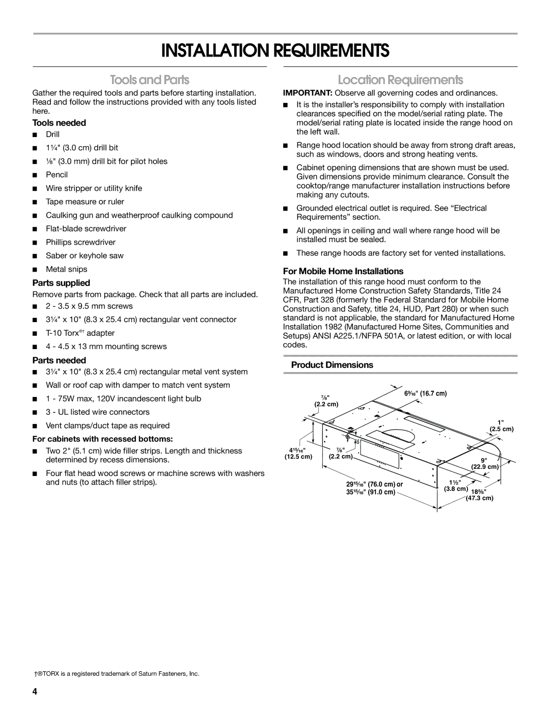
Installation is streamlined with the under-cabinet design, allowing these hoods to fit snugly beneath kitchen cabinets. Their flexible ducting options offer versatility depending on your kitchen layout, accommodating both vented and non-vented installation.
In summary, the Whirlpool UXT3036AY and UXT3030AY range hoods are high-quality appliances that combine powerful performance with stylish design. Their advanced ventilation technology, easy-to-clean features, modern aesthetics, and energy-efficient lighting make them an excellent addition to any kitchen, ensuring a pleasant cooking experience while maintaining a clean and inviting environment. Investing in either of these models guarantees an upgrade in both functionality and style for any home chef.