INSTALLATION REQUIREMENTS
Tools and Parts
Gather the required tools and parts before starting installation. Read and follow the instructions provided with any tools listed here.
Tools needed
■ | Tape measure | ■ | Wrench or pliers |
■ | Level | ■ | ³⁄₈" nut driver |
■ | Phillips screwdriver | ■ | Drill |
■ | ■ ¹⁄₈" (3.2 mm) drill bit | ||
Parts supplied
Check that all parts are included.
■3 -
■3 - Terminal lugs
■2 or 3 - Oven racks (depending on your model)
■2 - #12 x 1⁵⁄₈" screws (for mounting
■
Parts needed
If using a power supply cord:
■A UL listed power supply cord kit marked for use with ranges. The cord should be rated at 250 volts minimum, 40 amps or 50 amps that is marked for use with nominal 1³⁄₈" (3.5 cm) diameter connection opening and must end in ring terminals or
■A UL listed strain relief.
Check local codes. Check existing electrical supply. See “Electrical Requirements” section.
It is recommended that all electrical connections be made by a licensed, qualified electrical installer.
Location Requirements
IMPORTANT: Observe all governing codes and ordinances.
■It is the installer’s responsibility to comply with installation clearances specified on the model/serial rating plate. The model/serial rating plate is located on the
■The range should be located for convenient use in the kitchen.
■To eliminate the risk of burns or fire by reaching over heated surface units, cabinet storage space located above the surface units should be avoided. If cabinet storage is to be provided, the risk can be reduced by installing a range hood that projects horizontally a minimum of 5" (12.7 cm) beyond the bottom of the cabinets.
■Cabinet opening dimensions that are shown must be used. Given dimensions are minimum clearances.
■The floor
■Grounded electrical supply is required. See “Electrical Requirements” section.
IMPORTANT: To avoid damage to your cabinets, check with your builder or cabinet supplier to make sure that the materials used will not discolor, delaminate or sustain other damage. This oven has been designed in accordance with the requirements of UL and CSA International and complies with the maximum allowable wood cabinet temperatures of 194°F (90°C).
Mobile Home - Additional Installation Requirements
The installation of this range must conform to the Manufactured Home Construction and Safety Standard, Title 24 CFR, Part 3280 (formerly the Federal Standard for Mobile Home Construction and Safety, Title 24, HUD Part 280). When such standard is not applicable, the Standard for Manufactured Home Installations, ANSI A225.1/NFPA 501A or with local codes.
Mobile home installations require:
■When this range is installed in a mobile home, it must be secured to the floor during transit. Any method of securing the range is adequate as long as it conforms to the standards listed above.
■
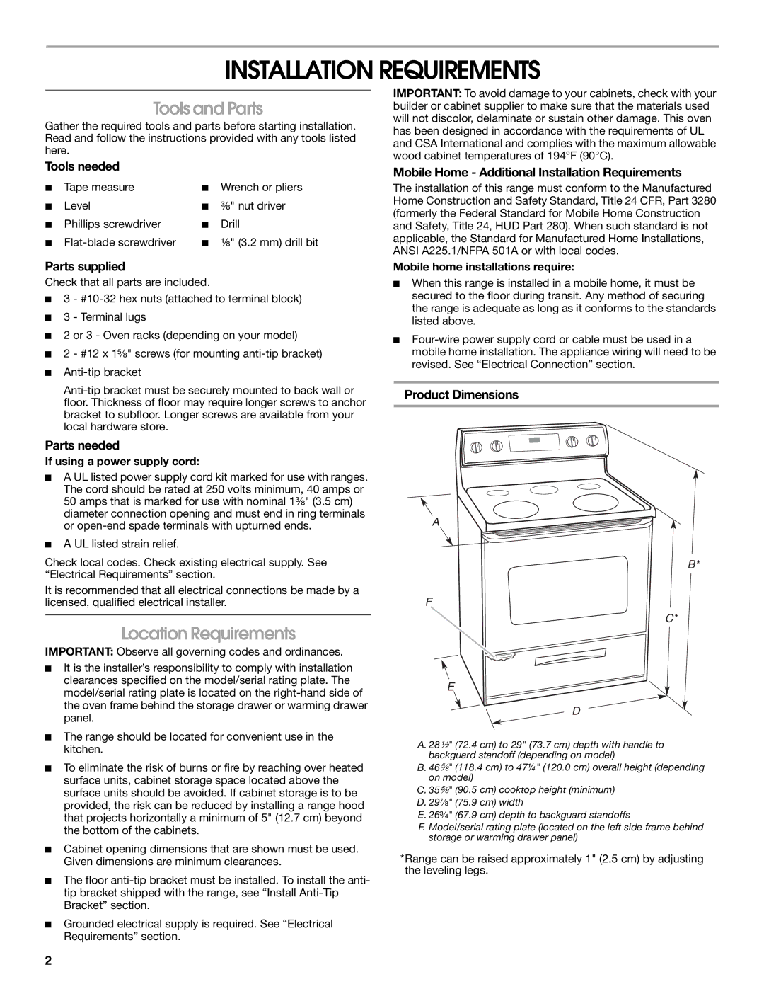
Product Dimensions
A
B*
F
C*
E
D
A. 28¹⁄₂" (72.4 cm) to 29" (73.7 cm) depth with handle to backguard standoff (depending on model)
B. 46⁵⁄₈" (118.4 cm) to 47¼" (120.0 cm) overall height (depending on model)
C. 35⁵⁄₈" (90.5 cm) cooktop height (minimum) D. 29⁷⁄₈" (75.9 cm) width
E. 26³⁄₄" (67.9 cm) depth to backguard standoffs
F. Model/serial rating plate (located on the left side frame behind storage or warming drawer panel)
*Range can be raised approximately 1" (2.5 cm) by adjusting the leveling legs.
2