4
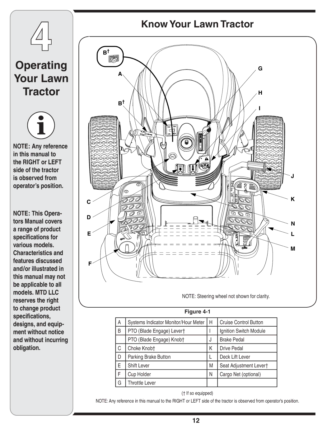
Know Your Lawn Tractor
Operating
Your Lawn
Tractor
NOTE: Any reference in this manual to the RIGHT or LEFT side of the tractor is observed from operator’s position.
NOTE: This Opera- tors Manual covers a range of product specifications for various models. Characteristics and features discussed and/or illustrated in this manual may not be applicable to all models. MTD LLC
B†
A
B†
C
D
E
F![]()
G
H
I
+
1/10 P
![]() P
P ![]()
![]()
![]()
![]()
![]()
![]()
![]()
![]()
![]()
![]()
![]()
![]()
![]()
![]()
![]()
![]()
![]()
![]()
![]()
![]()
![]()
![]()
![]()
![]()
![]()
![]()
![]()
![]()
![]()
![]()
![]()
![]()
![]()
![]()
![]()
![]()
![]()
![]()
![]()
![]()
![]() J
J
K |
N |
L |
M |
reserves the right to change product specifications, designs, and equip- ment without notice and without incurring obligation.
NOTE: Steering wheel not shown for clarity.
Figure
A | Systems Indicator Monitor/Hour Meter | H | Cruise Control Button |
B | PTO (Blade Engage) Lever† | I | Ignition Switch Module |
| PTO (Blade Engage) Knob† | J | Brake Pedal |
C | Choke Knob† | K | Drive Pedal |
D | Parking Brake Button | L | Deck Lift Lever |
E | Shift Lever | M | Seat Adjustment Lever† |
F | Cup Holder | N | Cargo Net (optional) |
G | Throttle Lever |
|
|
(† If so equipped)
NOTE: Any reference in this manual to the RIGHT or LEFT side of the tractor is observed from operator’s position.
12
