•Carefully pull the belt up and over the right hydrostatic cooling fan and then lift up and over the left hydrostatic cooling fan.
•Pull the drive belt out of the unit.
Installing Drive Belt
•Set the parking brake and insert drive belt up and over the left and right hydostatic cooling fans. Do not place the belt into the drive pulley groves at this time.
•Place the drive belt into the top groove of the engine pulley and route the belt to the inside of the idler pulley.
•Roll the belt up into the groove of the left drive pulley and roll the belt up into the groove of the right drive pulley.
•Make sure that the belt is seated in all pulley grooves and release the parking brake.
•The drive belt should be tightened by the idler pulley if the belt was installed correctly.
SECTION 7: MOWER DECK
Checking The Level Of The Mower Deck
Side to Side
•Position the
•Engage the parking brake and turn the ignition switch to the OFF position and remove key.
•Remove spark plug wire(s) from the spark plug(s).
•Raise the lift handle to the highest setting (7).
•Position the mower blades so they run perpendicular to the
Measurement
Blade
Figure 18
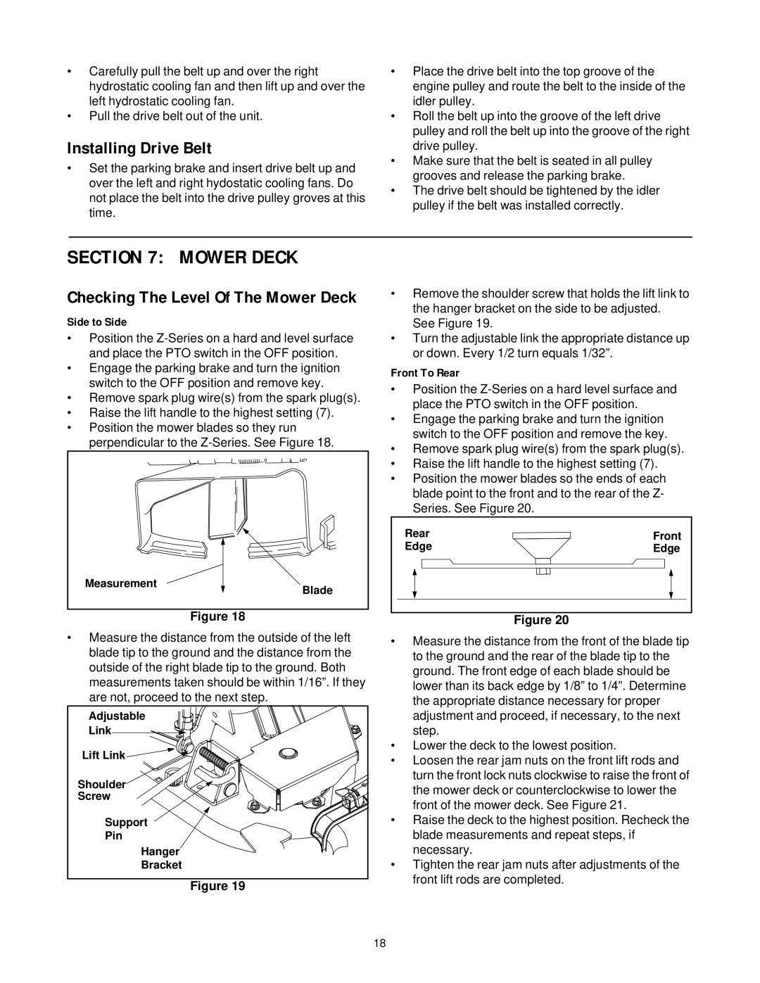
•Remove the shoulder screw that holds the lift link to the hanger bracket on the side to be adjusted.
See Figure 19.
•Turn the adjustable link the appropriate distance up or down. Every 1/2 turn equals 1/32”.
Front To Rear
•Position the
•Engage the parking brake and turn the ignition switch to the OFF position and remove the key.
•Remove spark plug wire(s) from the spark plug(s).
•Raise the lift handle to the highest setting (7).
•Position the mower blades so the ends of each blade point to the front and to the rear of the Z- Series. See Figure 20.
Rear | Front |
Edge | Edge |
Figure 20
• Measure the distance from the outside of the left | • |
blade tip to the ground and the distance from the |
|
outside of the right blade tip to the ground. Both |
|
measurements taken should be within 1/16”. If they |
|
are not, proceed to the next step. |
|
Adjustable |
| |
Link |
| |
Lift Link | • | |
• | ||
| ||
Shoulder |
| |
Screw |
| |
Support | • | |
Pin |
| |
Hanger | • | |
Bracket |
Figure 19
Measure the distance from the front of the blade tip to the ground and the rear of the blade tip to the ground. The front edge of each blade should be lower than its back edge by 1/8” to 1/4”. Determine the appropriate distance necessary for proper adjustment and proceed, if necessary, to the next step.
Lower the deck to the lowest position.
Loosen the rear jam nuts on the front lift rods and turn the front lock nuts clockwise to raise the front of the mower deck or counterclockwise to lower the front of the mower deck. See Figure 21.
Raise the deck to the highest position. Recheck the blade measurements and repeat steps, if necessary.
Tighten the rear jam nuts after adjustments of the front lift rods are completed.
18