NOTE
All wiring should be done according to local and national electrical codes.
RED BLUE
Common
Open on rise of temperature
WHITE ![]() Close on rise of temperature
Close on rise of temperature
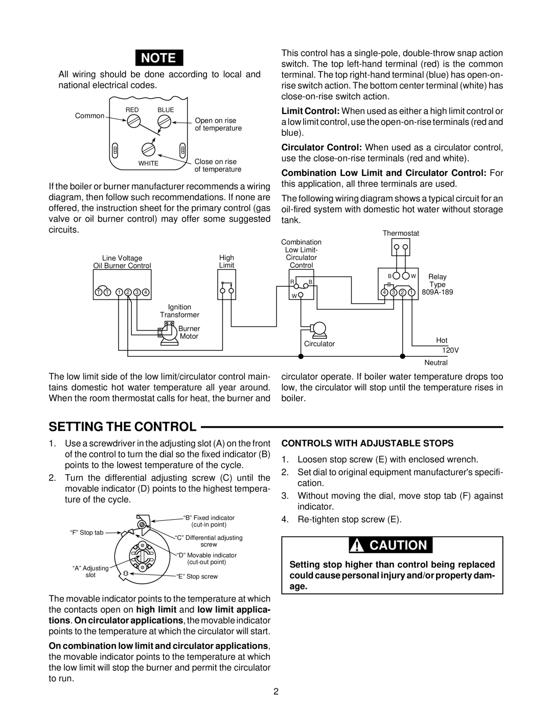
If the boiler or burner manufacturer recommends a wiring diagram, then follow such recommendations. If none are offered, the instruction sheet for the primary control (gas valve or oil burner control) may offer some suggested circuits.
This control has a
Limit Control: When used as either a high limit control or a low limit control, use the
Circulator Control: When used as a circulator control, use the
Combination Low Limit and Circulator Control: For this application, all three terminals are used.
The following wiring diagram shows a typical circuit for an
Line Voltage | High |
Oil Burner Control | Limit |
T T 1 2 3 4
Ignition
Transformer
Burner
Motor
Combination
Low Limit-
Circulator
Control
RB
W
Circulator
Thermostat
B ![]()
![]() W Relay Type
W Relay Type
4 3 2 1
Hot 120V
Neutral
The low limit side of the low limit/circulator control main- tains domestic hot water temperature all year around. When the room thermostat calls for heat, the burner and
SETTING THE CONTROL
circulator operate. If boiler water temperature drops too low, the circulator will stop until the temperature rises in boiler.
1.Use a screwdriver in the adjusting slot (A) on the front of the control to turn the dial so the fixed indicator (B) points to the lowest temperature of the cycle.
2.Turn the differential adjusting screw (C) until the movable indicator (D) points to the highest tempera- ture of the cycle.
“B” Fixed indicator
“F” Stop tab
“C” Differential adjusting screw
“D” Movable indicator
“A” Adjusting |
|
slot | “E” Stop screw |
The movable indicator points to the temperature at which the contacts open on high limit and low limit applica- tions. On circulator applications, the movable indicator points to the temperature at which the circulator will start.
On combination low limit and circulator applications, the movable indicator points to the temperature at which the low limit will stop the burner and permit the circulator to run.
CONTROLS WITH ADJUSTABLE STOPS
1.Loosen stop screw (E) with enclosed wrench.
2.Set dial to original equipment manufacturer's specifi- cation.
3.Without moving the dial, move stop tab (F) against indicator.
4.
!CAUTION
Setting stop higher than control being replaced could cause personal injury and/or property dam- age.
2
