
1D30(W), 1C30(W) specifications
White Rodgers is a well-known brand in the HVAC (heating, ventilation, and air conditioning) industry, and its 1D30(W) and 1C30(W) series thermostats are notable for their innovative features and reliable performance. These thermostats are designed to provide precise temperature control and enhance the overall efficiency of heating and cooling systems in both residential and commercial settings.The White Rodgers 1D30(W) model is an analog thermostat that offers a user-friendly interface, making it easy for homeowners and technicians alike to operate and program. With a clear and simple design, this thermostat allows users to adjust the temperature settings effortlessly, promoting convenience and comfort. It is compatible with various heating systems, including gas, oil, and electric furnaces, which makes it a versatile option for many applications.
On the other hand, the White Rodgers 1C30(W) model represents a more advanced option, incorporating digital technology for added functionality. This thermostat features an LCD display that provides clear visibility of temperature settings and system statuses. The 1C30(W) also includes programmable features, allowing users to set different temperatures based on their schedules. This capability not only provides comfort but also helps save energy by reducing unnecessary heating or cooling when it’s not needed.
Both models come equipped with high-quality sensors that ensure accurate temperature readings. This accuracy is crucial for maintaining consistent comfort levels within a space. Additionally, these thermostats feature adjustable settings, enabling fine-tuning according to personal preferences or specific environmental conditions.
One significant characteristic of both the 1D30(W) and 1C30(W) is their compatibility with multi-stage heating and cooling systems. This flexibility makes them suitable for a wide range of HVAC setups, ensuring effective performance regardless of the type of equipment in use.
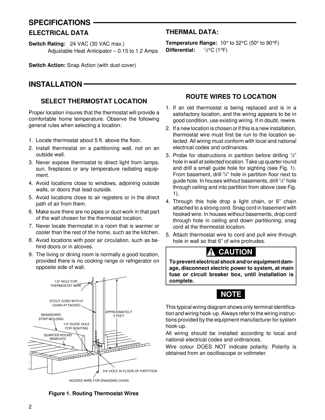
Furthermore, these thermostats are designed for easy installation and maintenance, making them an appealing choice for both DIY enthusiasts and professional installers. Their durable construction ensures long-lasting reliability, providing peace of mind for users.
In conclusion, the White Rodgers 1D30(W) and 1C30(W) thermostats represent excellent options for individuals seeking effective temperature control solutions for their heating and cooling systems. With their user-friendly features, advanced technologies, and reliable performance, they continue to be trusted choices in the HVAC industry.