INSTALLATION
ATTACH SUBBASE TO WALL
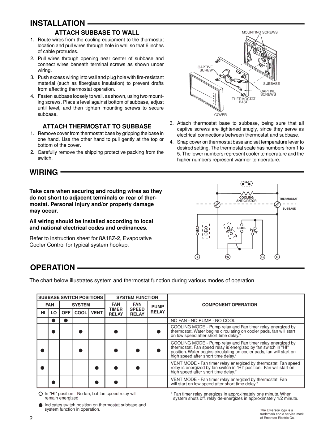
1.Route wires from the cooling equipment to the thermostat location and pull wires through hole in wall so that 6 inches of cable protrudes.
2.Pull wires through opening near center of subbase and connect wires beneath terminal screws as shown under wiring.
3.Push excess wiring into wall and plug hole with
4.Fasten subbase loosely to wall, as shown, using two mount- ing screws. Place a level against bottom of subbase, adjust until level, and then tighten mounting screws to secure subbase.
ATTACH THERMOSTAT TO SUBBASE
1.Remove cover from thermostat base by gripping the base in one hand. Use the other hand to pull gently at the top or bottom of the cover.
2.Carefully remove the shipping protective packing from the switch.
MOUNTING SCREWS
CAPTIVE
SCREW ![]()
SUBBASE
![]() CAPTIVE
CAPTIVE
SCREWS
THERMOSTAT
BASE
COVER
3.Attach thermostat base to subbase, being sure that all captive screws are tightened snugly, since they serve as electrical connections between thermostat and subbase.
4.Snap cover on thermostat base and set temperature lever to desired setting. The thermostat scale has numbers from 1 to 5. The lower numbers represent cooler temperature and the higher numbers represent warmer temperature.
WIRING
Take care when securing and routing wires so they do not short to adjacent terminals or rear of ther- mostat. Personal injury and/or property damage may occur.
All wiring should be installed according to local and national electrical codes and ordinances.
Refer to instruction sheet for
COOLING |
ANTICIPATOR |
HI LO | FF | COOL | V | E | N |
| |||||
| O |
|
|
| |
|
|
|
|
| T |
THERMOSTAT
SUBBASE
OPERATION
YWG R
The chart below illustrates system and thermostat function during various modes of operation.
| SUBBASE SWITCH POSITIONS | SYSTEM FUNCTION |
| ||||||
|
|
|
|
|
|
|
|
|
|
| FAN | SYSTEM | FAN | FAN | PUMP | COMPONENT OPERATION | |||
|
|
|
|
|
| TIMER | SPEED |
| |
| HI | LO | OFF | COOL | VENT | RELAY |
| ||
| RELAY | RELAY |
| ||||||
|
|
|
|
|
|
|
| ||
|
|
|
|
|
|
|
|
| NO FAN - NO PUMP - NO COOL |
|
|
|
|
|
|
|
|
| COOLING MODE - Pump relay and Fan timer relay energized by |
|
|
|
|
|
|
|
|
| thermostat. Water begins circulating on cooler pads, fan will start |
|
|
|
|
|
|
|
|
| on low speed after short time delay.* |
|
|
|
|
|
|
|
|
|
|
|
|
|
|
|
|
|
|
| COOLING MODE - Pump relay and Fan timer relay energized by |
|
|
|
|
|
|
|
|
| thermostat. Fan speed relay is energized by fan switch in "HI" |
|
|
|
|
|
|
|
|
| position. Water begins circulating on cooler pads, fan will start on |
|
|
|
|
|
|
|
|
| high speed after short time delay.* |
|
|
|
|
|
|
|
|
|
|
|
|
|
|
|
|
|
|
| VENT MODE - Fan timer relay energized by thermostat. Fan speed |
|
|
|
|
|
|
|
|
| relay is energized by fan switch in "HI" position. Fan will start on |
|
|
|
|
|
|
|
|
| high speed after short time delay.* |
|
|
|
|
|
|
|
|
|
|
|
|
|
|
|
|
|
|
| VENT MODE - Fan timer relay energized by thermostat. Fan |
|
|
|
|
|
|
|
|
| will start on low speed after short time delay.* |
|
|
|
|
|
|
|
|
|
|
| In "HI" position - No fan, but fan speed relay will |
| * Fan timer relay energizes in approximately one minute. When | ||||||
| remain energized |
|
|
| system shuts off, relay | ||||
| Indicates switch position on thermostat subbase and |
|
| ||||||
| system function in operation. |
|
|
| The Emerson logo is a | ||||
2 |
|
|
|
|
|
|
|
| trademark and a service mark |
|
|
|
|
|
|
|
| of Emerson Electric Co. | |