CB O

NOTE

For 2-wire Heat only, attach to RH and W


JUMPER


WIRE


Y

G

W

RC RH

THERMOSTAT

SYSTEM


Fan

Heating


Relay

System


Hot


24 VAC

120 VAC


Neutral


TRANSFORMER

THERMOSTAT

CB O

Y

G

W

RC RH

Cooling

Fan

Heating

System

Relay

System


SYSTEM


Hot


24 VAC


120 VAC


Neutral


HEATING

TRANSFORMER

24 VAC


Hot


120 VAC

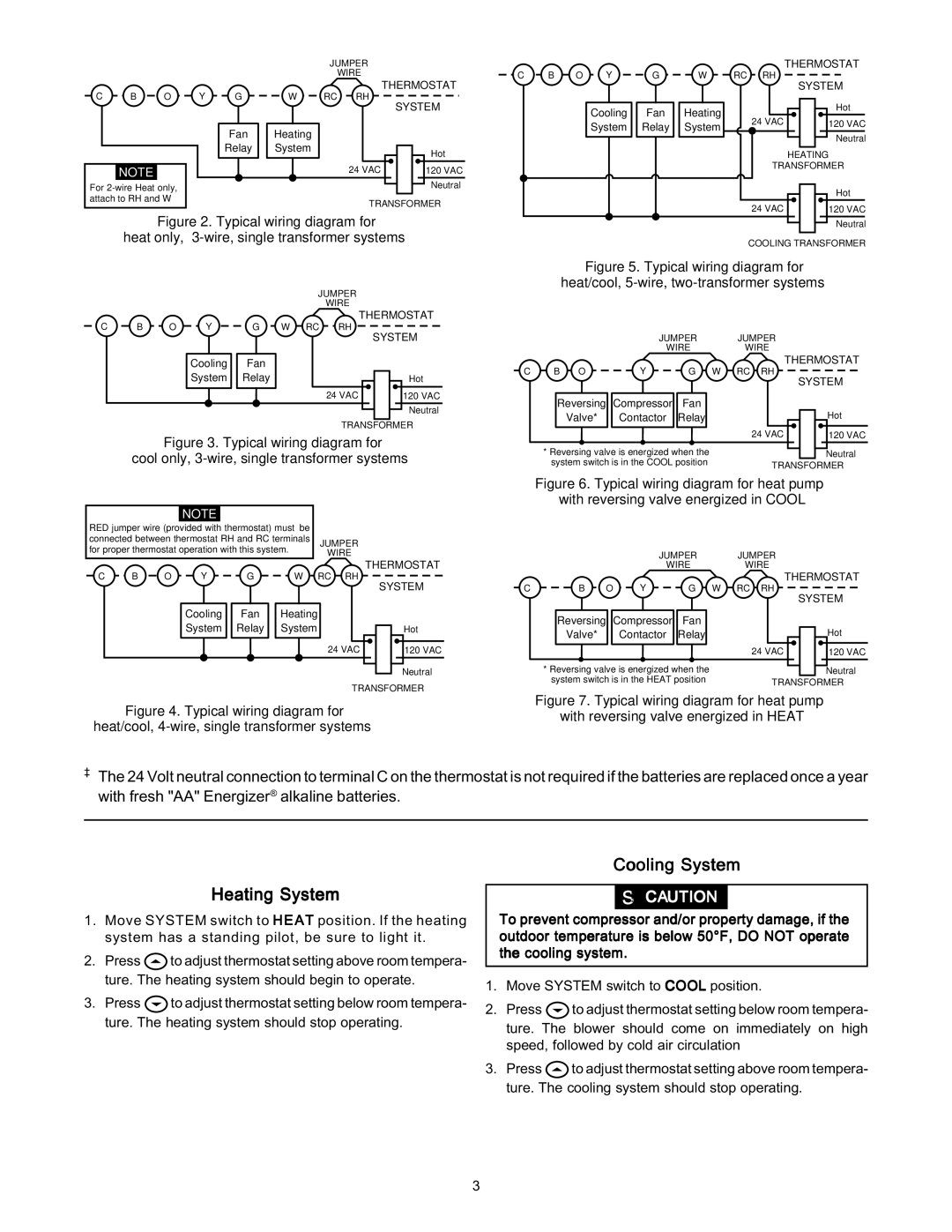
Figure 2. Typical wiring diagram for

heat only, 3-wire, single transformer systems

JUMPER

WIRE

C


Y


THERMOSTAT


B

O


G

W

RC

RH


SYSTEM


Cooling


Fan


System


Relay


Hot


24 VAC


120 VAC


Neutral


TRANSFORMER


Figure 3. Typical wiring diagram for


cool only, 3-wire, single transformer systems


NOTE


RED jumper wire (provided with thermostat) must be


connected between thermostat RH and RC terminals


JUMPER


for proper thermostat operation with this system.


WIRE


C

B

O


Y


G

W


RC

RH

THERMOSTAT


SYSTEM


Cooling


Fan


Heating


System


Relay


System


Hot


24 VAC


120 VAC


Neutral


TRANSFORMER


Neutral

COOLING TRANSFORMER

Figure 5. Typical wiring diagram for

heat/cool, 5-wire, two-transformer systems

JUMPER JUMPER

WIREWIRE

C

B O


Y

G

W

RC RH

THERMOSTAT


SYSTEM


Reversing

Compressor

Fan


Valve*


Contactor

Relay


Hot


24 VAC

120 VAC


* Reversing valve is energized when the


Neutral


system switch is in the COOL position


TRANSFORMER


Figure 6. Typical wiring diagram for heat pump


with reversing valve energized in COOL


JUMPER


JUMPER


WIRE


WIRE


C

B O

Y

G

W

RC RH

THERMOSTAT

SYSTEM


Reversing

Compressor

Fan


Valve*


Contactor

Relay


Hot


24 VAC

120 VAC


* Reversing valve is energized when the


Neutral


system switch is in the HEAT position


TRANSFORMER

Figure 7. Typical wiring diagram for heat pump

Figure 4. Typical wiring diagram forwith reversing valve energized in HEAT heat/cool, 4-wire, single transformer systems

The 24 Volt neutral connection to terminal C on the thermostat is not required if the batteries are replaced once a year with fresh "AA" Energizer® alkaline batteries.

Heating System

1.Move SYSTEM switch to HEAT position. If the heating system has a standing pilot, be sure to light it.

2.Press to adjust thermostat setting above room tempera- ture. The heating system should begin to operate.

3.Press to adjust thermostat setting below room tempera- ture. The heating system should stop operating.

Cooling System

! CAUTION

To prevent compressor and/or property damage, if the outdoor temperature is below 50°F, DO NOT operate the cooling system.

1.Move SYSTEM switch to COOL position.

2.Press to adjust thermostat setting below room tempera- ture. The blower should come on immediately on high speed, followed by cold air circulation

3.Press to adjust thermostat setting above room tempera- ture. The cooling system should stop operating.

3

Page 3
Image 3
White Rodgers 1F87-361 specifications Heating System, Cooling System

1F87-361 specifications

The White Rodgers 1F87-361 is a distinguished programmable thermostat designed to enhance energy efficiency and comfort in residential heating and cooling systems. With a user-friendly interface and a range of advanced features, this device stands out in the marketplace for its reliability and ease of use.

One of the main features of the 1F87-361 is its intuitive 7-day programmable scheduling. This allows users to customize their heating and cooling preferences for each day of the week, ensuring optimal comfort at all times. Additionally, the device is equipped with a backlit display, making it easy to read settings and temperatures, even in low-light conditions.

The technology harnessed in the 1F87-361 includes advanced temperature control algorithms, which optimize the heating and cooling cycles of HVAC systems. This not only helps to maintain stable indoor temperatures but also contributes to significant energy savings. The thermostat is designed to be compatible with most heating and cooling systems, including gas, oil, and electric furnaces, as well as heat pumps.

Moreover, the White Rodgers 1F87-361 incorporates a built-in adaptive recovery feature. This intelligent technology learns the thermal characteristics of your home, allowing the thermostat to anticipate the time needed to reach the desired temperature. This proactive approach reduces energy waste while ensuring that your living space is comfortable when you need it the most.

Another noteworthy characteristic is the device's ability to provide real-time temperature readings and system status updates. Users can easily monitor their home's temperature remotely and make adjustments as required. This is complemented by the optional Wi-Fi connectivity feature, which allows integration with smart home systems and mobile applications for even greater control and convenience.

The White Rodgers 1F87-361 also prioritizes user convenience with its simple installation process. With clear instructions and a straightforward wiring design, both DIY enthusiasts and professional installers can set it up with minimal hassle. Additionally, the device supports a battery backup system, ensuring continued operation during power outages.

In conclusion, the White Rodgers 1F87-361 programmable thermostat combines advanced technology with user-friendly features to provide an optimal heating and cooling experience. Its programmable scheduling, adaptive recovery, and user-friendly design make it a valuable addition to any home seeking enhanced energy efficiency and comfort.