
1F87-51 specifications
The White Rodgers 1F87-51 is a highly versatile smart thermostat designed to enhance home energy management. Offering advanced features that cater to both comfort and efficiency, it stands out in its category due to its user-friendly interface and innovative technology.One of the main features of the 1F87-51 is its compatibility with a wide range of heating and cooling systems. It supports conventional systems such as gas, oil, and electric furnaces, as well as heat pumps and multi-stage systems. This versatility makes it a suitable choice for a diverse array of household setups. Additionally, the thermostat can manage up to two-stage heating and two-stage cooling simultaneously, providing precise control over home temperatures throughout the year.
The 1F87-51 employs a simple yet effective programming system, allowing users to create schedules that fit their lifestyle. This programmable capability means users can set specific heating and cooling times, optimizing energy usage and ensuring comfort when it's needed most. With up to four programmable periods per day, the thermostat allows for detailed customization. Furthermore, it features a "hold" function, letting homeowners maintain a set temperature indefinitely, bypassing programmed settings whenever required.
In terms of technology, the White Rodgers 1F87-51 utilizes an intuitive digital display that is easy to read and operate. This backlit display provides clear visibility in low-light conditions, making adjustments simple. The thermostat is also equipped with an automatic changeover functionality. This feature seamlessly transitions between heating and cooling modes, maintaining a stable indoor environment without requiring manual intervention.
Energy efficiency is a key characteristic of the 1F87-51. With its advanced algorithms, the thermostat learns user patterns and automatically adjusts settings to save energy, ultimately resulting in reduced utility bills. Some users may also appreciate its Energy Save function, which can pause heating or cooling during periods of inactivity.
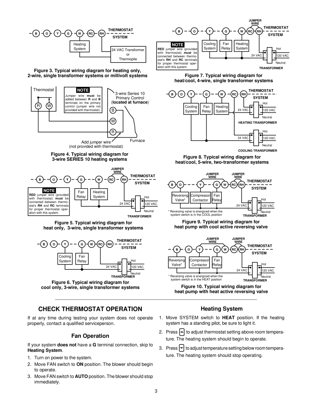
Installation of the 1F87-51 is straightforward, with a clear wiring diagram, allowing even those with basic DIY skills to set it up.
Overall, the White Rodgers 1F87-51 smart thermostat combines flexibility, ease of use, and energy efficiency, making it an ideal choice for homeowners looking to modernize their climate control systems. With its ability to adapt to individual needs, it ensures a comfortable living environment while promoting energy savings.