Return Air without Economizer — The sampling tube is located across the return air opening on the unit basepan. See Fig. 19. The holes in the sampling tube face downward, into the return air stream. The sampling tube is connected via tubing to the return air sensor that is mounted on a bracket high on the partition between return filter and controller location. (This sensor is shipped in a flat-mounting location. Installation requires that this sensor be relocated to its operating location and the tubing to the sampling tube be connected. See installation steps below.)

Return Air Detector module (shipping position shown)*

Controller module

Return Air Detector Sampling Tube

*RA detector must be moved from shipping position to operating position by installer

C07307

Fig. 19 - Typical Return Air Detector Location

Return Air with Economizer — The sampling tube is inserted through the side plates of the economizer housing, placing it across the return air opening on the unit basepan. See Fig. 20. The holes in the sampling tube face downward, into the return air stream. The sampling tube is connected via tubing to the return air sensor that is mounted on a bracket high on the partition between return filter and controller location. (This sensor is shipped in a flat-mounting location. Installation requires that this sensor be relocated to its operating location and the tubing to the sampling tube be connected. See installation steps below.)

Return Air

Sampling Tube

C08129

Fig. 20 - Return Air Sampling Tube Location

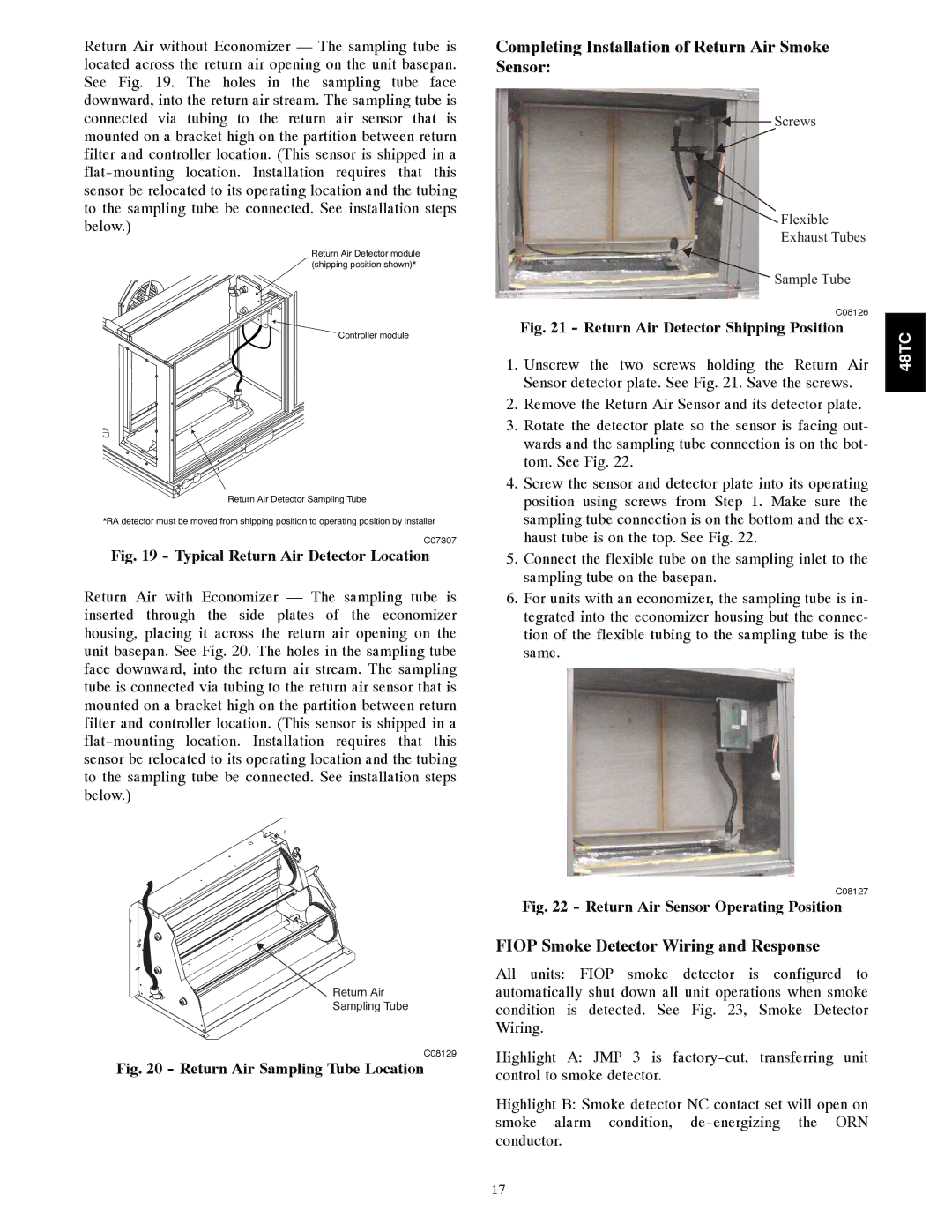
Completing Installation of Return Air Smoke Sensor:

Screws


Flexible


Exhaust Tubes


Sample Tube


C08126


Fig. 21 - Return Air Detector Shipping Position

48TC

1.

Unscrew the two screws holding the Return Air


Sensor detector plate. See Fig. 21. Save the screws.


2.

Remove the Return Air Sensor and its detector plate.


3.

Rotate the detector plate so the sensor is facing out-


wards and the sampling tube connection is on the bot-


tom. See Fig. 22.


4.

Screw the sensor and detector plate into its operating


position using screws from Step 1. Make sure the


sampling tube connection is on the bottom and the ex-


haust tube is on the top. See Fig. 22.


5.

Connect the flexible tube on the sampling inlet to the


sampling tube on the basepan.


6.

For units with an economizer, the sampling tube is in-


tegrated into the economizer housing but the connec-


tion of the flexible tubing to the sampling tube is the same.

C08127

Fig. 22 - Return Air Sensor Operating Position

FIOP Smoke Detector Wiring and Response

All units: FIOP smoke detector is configured to automatically shut down all unit operations when smoke condition is detected. See Fig. 23, Smoke Detector Wiring.

Highlight A: JMP 3 is factory-cut, transferring unit control to smoke detector.

Highlight B: Smoke detector NC contact set will open on smoke alarm condition, de-energizing the ORN conductor.

17

Page 17
Image 17
Carrier 48TCA04---A12 appendix Completing Installation of Return Air Smoke Sensor, Fiop Smoke Detector Wiring and Response

48TCA04---A12 specifications

The Carrier 48TCA04---A12 is a high-efficiency rooftop air conditioning unit designed for commercial and industrial applications. Known for its reliability and performance, this model features advanced technologies that cater to diverse climate control needs.

One of the standout features of the Carrier 48TCA04---A12 is its excellent energy efficiency, which adheres to the stringent standards set by the U.S. Environmental Protection Agency. The unit utilizes a highly efficient scroll compressor combined with state-of-the-art heat exchanger technology, allowing it to operate with minimal energy consumption while providing powerful cooling capabilities.

The unit comes equipped with a robust and durable design, built to withstand various environmental conditions. Its weather-resistant cabinet is constructed from high-quality materials, ensuring long-lasting performance even in harsh climates. Additionally, the unit features a galvanized steel structure with a powder-coated finish, further enhancing its resistance to corrosion and wear.

In terms of technologies, the Carrier 48TCA04---A12 incorporates advanced controls that promote optimal performance. The unit supports Carrier's smart connectivity options, facilitating remote monitoring and adjustments via smart devices. This feature ensures convenient energy management and allows maintenance teams to access performance data, leading to proactive service interventions.

Another important characteristic of this unit is its quiet operation. The design includes sound-reducing insulation and a well-engineered airflow system, minimizing noise levels to create a more comfortable indoor environment. This is particularly important for commercial spaces such as offices and retail environments, where a tranquil atmosphere is critical for customer satisfaction and productivity.

The Carrier 48TCA04---A12 also offers diverse application flexibility, making it suitable for various locations, from small retail stores to large warehouses. With several tonnage options available, users can select a model that perfectly aligns with their specific cooling needs. Additionally, the unit can be easily integrated with existing HVAC systems, providing a seamless solution for upgrading or retrofitting older installations.

To sum up, the Carrier 48TCA04---A12 rooftop air conditioning unit stands out due to its exceptional energy efficiency, durable construction, advanced technology, and quiet operation, making it a reliable choice for commercial and industrial cooling solutions. Its flexibility and smart technology integrations ensure that it meets a wide range of climate control requirements effectively.