48TC

N1


EXH

TR

TR1


N


Set


2V

10V


P1


EXH


24

24 Vac


Vac

COM


P


Min

HOT

_

T1


Pos

+


T

Open


DCV

1

2


Max


2V

10V


AQ1

DCV


5


AQ


DCV


4

SO+


Set

3

SO

2V

10V


SR+

Free


EF

EF1


Cool


SR

B

C


A

D


C06038

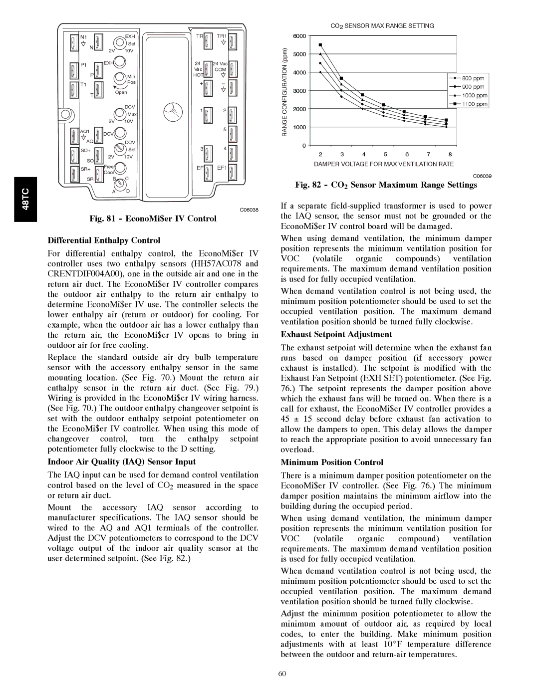
Fig. 81 - EconoMi$er IV Control

Differential Enthalpy Control

For differential enthalpy control, the EconoMi$er IV controller uses two enthalpy sensors (HH57AC078 and CRENTDIF004A00), one in the outside air and one in the return air duct. The EconoMi$er IV controller compares the outdoor air enthalpy to the return air enthalpy to determine EconoMi$er IV use. The controller selects the lower enthalpy air (return or outdoor) for cooling. For example, when the outdoor air has a lower enthalpy than the return air, the EconoMi$er IV opens to bring in outdoor air for free cooling.

Replace the standard outside air dry bulb temperature sensor with the accessory enthalpy sensor in the same mounting location. (See Fig. 70.) Mount the return air enthalpy sensor in the return air duct. (See Fig. 79.) Wiring is provided in the EconoMi$er IV wiring harness. (See Fig. 70.) The outdoor enthalpy changeover setpoint is set with the outdoor enthalpy setpoint potentiometer on the EconoMi$er IV controller. When using this mode of changeover control, turn the enthalpy setpoint potentiometer fully clockwise to the D setting.

Indoor Air Quality (IAQ) Sensor Input

The IAQ input can be used for demand control ventilation control based on the level of CO2 measured in the space or return air duct.

Mount the accessory IAQ sensor according to manufacturer specifications. The IAQ sensor should be wired to the AQ and AQ1 terminals of the controller. Adjust the DCV potentiometers to correspond to the DCV voltage output of the indoor air quality sensor at the user-determined setpoint. (See Fig. 82.)

CO2 SENSOR MAX RANGE SETTING


6000


(ppm)

5000


CONFIGURATION

4000


800 ppm


3000


900 ppm


1000 ppm


2000


1100 ppm


RANGE

1000


0


2

3

4

5

6

7

8


DAMPER VOLTAGE FOR MAX VENTILATION RATE

C06039

Fig. 82 - CO2 Sensor Maximum Range Settings

If a separate field-supplied transformer is used to power the IAQ sensor, the sensor must not be grounded or the EconoMi$er IV control board will be damaged.

When using demand ventilation, the minimum damper position represents the minimum ventilation position for VOC (volatile organic compounds) ventilation requirements. The maximum demand ventilation position is used for fully occupied ventilation.

When demand ventilation control is not being used, the minimum position potentiometer should be used to set the occupied ventilation position. The maximum demand ventilation position should be turned fully clockwise.

Exhaust Setpoint Adjustment

The exhaust setpoint will determine when the exhaust fan runs based on damper position (if accessory power exhaust is installed). The setpoint is modified with the Exhaust Fan Setpoint (EXH SET) potentiometer. (See Fig. 76.) The setpoint represents the damper position above which the exhaust fans will be turned on. When there is a call for exhaust, the EconoMi$er IV controller provides a 45 ± 15 second delay before exhaust fan activation to allow the dampers to open. This delay allows the damper to reach the appropriate position to avoid unnecessary fan overload.

Minimum Position Control

There is a minimum damper position potentiometer on the EconoMi$er IV controller. (See Fig. 76.) The minimum damper position maintains the minimum airflow into the building during the occupied period.

When using demand ventilation, the minimum damper position represents the minimum ventilation position for VOC (volatile organic compound) ventilation requirements. The maximum demand ventilation position is used for fully occupied ventilation.

When demand ventilation control is not being used, the minimum position potentiometer should be used to set the occupied ventilation position. The maximum demand ventilation position should be turned fully clockwise.

Adjust the minimum position potentiometer to allow the minimum amount of outdoor air, as required by local codes, to enter the building. Make minimum position adjustments with at least 10_F temperature difference between the outdoor and return-air temperatures.

60

Page 60
Image 60
Carrier 48TCA04---A12 appendix Indoor Air Quality IAQ Sensor Input, Exhaust Setpoint Adjustment, Minimum Position Control

48TCA04---A12 specifications

The Carrier 48TCA04---A12 is a high-efficiency rooftop air conditioning unit designed for commercial and industrial applications. Known for its reliability and performance, this model features advanced technologies that cater to diverse climate control needs.

One of the standout features of the Carrier 48TCA04---A12 is its excellent energy efficiency, which adheres to the stringent standards set by the U.S. Environmental Protection Agency. The unit utilizes a highly efficient scroll compressor combined with state-of-the-art heat exchanger technology, allowing it to operate with minimal energy consumption while providing powerful cooling capabilities.

The unit comes equipped with a robust and durable design, built to withstand various environmental conditions. Its weather-resistant cabinet is constructed from high-quality materials, ensuring long-lasting performance even in harsh climates. Additionally, the unit features a galvanized steel structure with a powder-coated finish, further enhancing its resistance to corrosion and wear.

In terms of technologies, the Carrier 48TCA04---A12 incorporates advanced controls that promote optimal performance. The unit supports Carrier's smart connectivity options, facilitating remote monitoring and adjustments via smart devices. This feature ensures convenient energy management and allows maintenance teams to access performance data, leading to proactive service interventions.

Another important characteristic of this unit is its quiet operation. The design includes sound-reducing insulation and a well-engineered airflow system, minimizing noise levels to create a more comfortable indoor environment. This is particularly important for commercial spaces such as offices and retail environments, where a tranquil atmosphere is critical for customer satisfaction and productivity.

The Carrier 48TCA04---A12 also offers diverse application flexibility, making it suitable for various locations, from small retail stores to large warehouses. With several tonnage options available, users can select a model that perfectly aligns with their specific cooling needs. Additionally, the unit can be easily integrated with existing HVAC systems, providing a seamless solution for upgrading or retrofitting older installations.

To sum up, the Carrier 48TCA04---A12 rooftop air conditioning unit stands out due to its exceptional energy efficiency, durable construction, advanced technology, and quiet operation, making it a reliable choice for commercial and industrial cooling solutions. Its flexibility and smart technology integrations ensure that it meets a wide range of climate control requirements effectively.