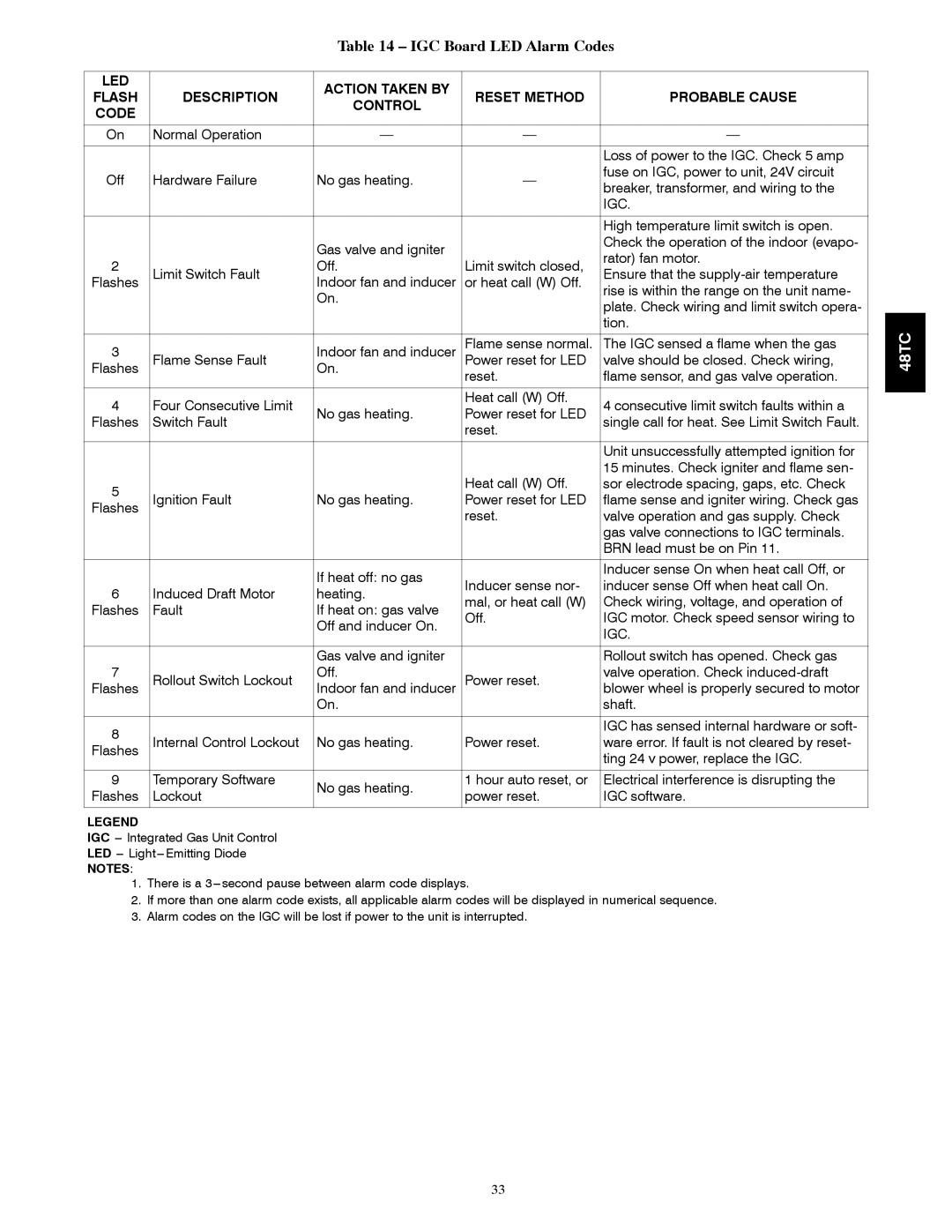
Table 14 – IGC Board LED Alarm Codes

LED

DESCRIPTION

ACTION TAKEN BY

RESET METHOD

PROBABLE CAUSE

FLASH

CONTROL

CODE


On

Normal Operation


Loss of power to the IGC. Check 5 amp

Off

Hardware Failure

No gas heating.

fuse on IGC, power to unit, 24V circuit

breaker, transformer, and wiring to the


IGC.


High temperature limit switch is open.


Gas valve and igniter


Check the operation of the indoor (evapo-


rator) fan motor.

2

Limit Switch Fault

Off.

Limit switch closed,

Ensure that the supply-air temperature

Flashes

Indoor fan and inducer

or heat call (W) Off.


On.


rise is within the range on the unit name-


plate. Check wiring and limit switch opera-


tion.


3

Flame Sense Fault

Indoor fan and inducer

Flame sense normal.

The IGC sensed a flame when the gas

Flashes

On.

Power reset for LED

valve should be closed. Check wiring,


reset.

flame sensor, and gas valve operation.

4

Four Consecutive Limit

No gas heating.

Heat call (W) Off.

4 consecutive limit switch faults within a

Power reset for LED

Flashes

Switch Fault

single call for heat. See Limit Switch Fault.


reset.


Unit unsuccessfully attempted ignition for


Heat call (W) Off.

15 minutes. Check igniter and flame sen-

5

Ignition Fault

No gas heating.

sor electrode spacing, gaps, etc. Check

Power reset for LED

flame sense and igniter wiring. Check gas

Flashes


reset.

valve operation and gas supply. Check


gas valve connections to IGC terminals.


BRN lead must be on Pin 11.


If heat off: no gas

Inducer sense nor-

Inducer sense On when heat call Off, or

6

Induced Draft Motor

inducer sense Off when heat call On.

heating.

mal, or heat call (W)

Check wiring, voltage, and operation of

Flashes

Fault

If heat on: gas valve

Off.

IGC motor. Check speed sensor wiring to


Off and inducer On.


IGC.


7


Gas valve and igniter


Rollout switch has opened. Check gas

Rollout Switch Lockout

Off.

Power reset.

valve operation. Check induced-draft

Flashes

Indoor fan and inducer

blower wheel is properly secured to motor


On.


shaft.


8

Internal Control Lockout

No gas heating.

Power reset.

IGC has sensed internal hardware or soft-

ware error. If fault is not cleared by reset-

Flashes


ting 24 v power, replace the IGC.

9

Temporary Software

No gas heating.

1 hour auto reset, or

Electrical interference is disrupting the

Flashes

Lockout

power reset.

IGC software.


LEGEND

IGC --- Integrated Gas Unit Control

LED --- Light---Emitting Diode

NOTES:

1.There is a 3---second pause between alarm code displays.

2.If more than one alarm code exists, all applicable alarm codes will be displayed in numerical sequence.

3.Alarm codes on the IGC will be lost if power to the unit is interrupted.

48TC

33

Page 33
Image 33
Carrier 48TCA04---A12 appendix IGC Board LED Alarm Codes, Igc

48TCA04---A12 specifications

The Carrier 48TCA04---A12 is a high-efficiency rooftop air conditioning unit designed for commercial and industrial applications. Known for its reliability and performance, this model features advanced technologies that cater to diverse climate control needs.

One of the standout features of the Carrier 48TCA04---A12 is its excellent energy efficiency, which adheres to the stringent standards set by the U.S. Environmental Protection Agency. The unit utilizes a highly efficient scroll compressor combined with state-of-the-art heat exchanger technology, allowing it to operate with minimal energy consumption while providing powerful cooling capabilities.

The unit comes equipped with a robust and durable design, built to withstand various environmental conditions. Its weather-resistant cabinet is constructed from high-quality materials, ensuring long-lasting performance even in harsh climates. Additionally, the unit features a galvanized steel structure with a powder-coated finish, further enhancing its resistance to corrosion and wear.

In terms of technologies, the Carrier 48TCA04---A12 incorporates advanced controls that promote optimal performance. The unit supports Carrier's smart connectivity options, facilitating remote monitoring and adjustments via smart devices. This feature ensures convenient energy management and allows maintenance teams to access performance data, leading to proactive service interventions.

Another important characteristic of this unit is its quiet operation. The design includes sound-reducing insulation and a well-engineered airflow system, minimizing noise levels to create a more comfortable indoor environment. This is particularly important for commercial spaces such as offices and retail environments, where a tranquil atmosphere is critical for customer satisfaction and productivity.

The Carrier 48TCA04---A12 also offers diverse application flexibility, making it suitable for various locations, from small retail stores to large warehouses. With several tonnage options available, users can select a model that perfectly aligns with their specific cooling needs. Additionally, the unit can be easily integrated with existing HVAC systems, providing a seamless solution for upgrading or retrofitting older installations.

To sum up, the Carrier 48TCA04---A12 rooftop air conditioning unit stands out due to its exceptional energy efficiency, durable construction, advanced technology, and quiet operation, making it a reliable choice for commercial and industrial cooling solutions. Its flexibility and smart technology integrations ensure that it meets a wide range of climate control requirements effectively.