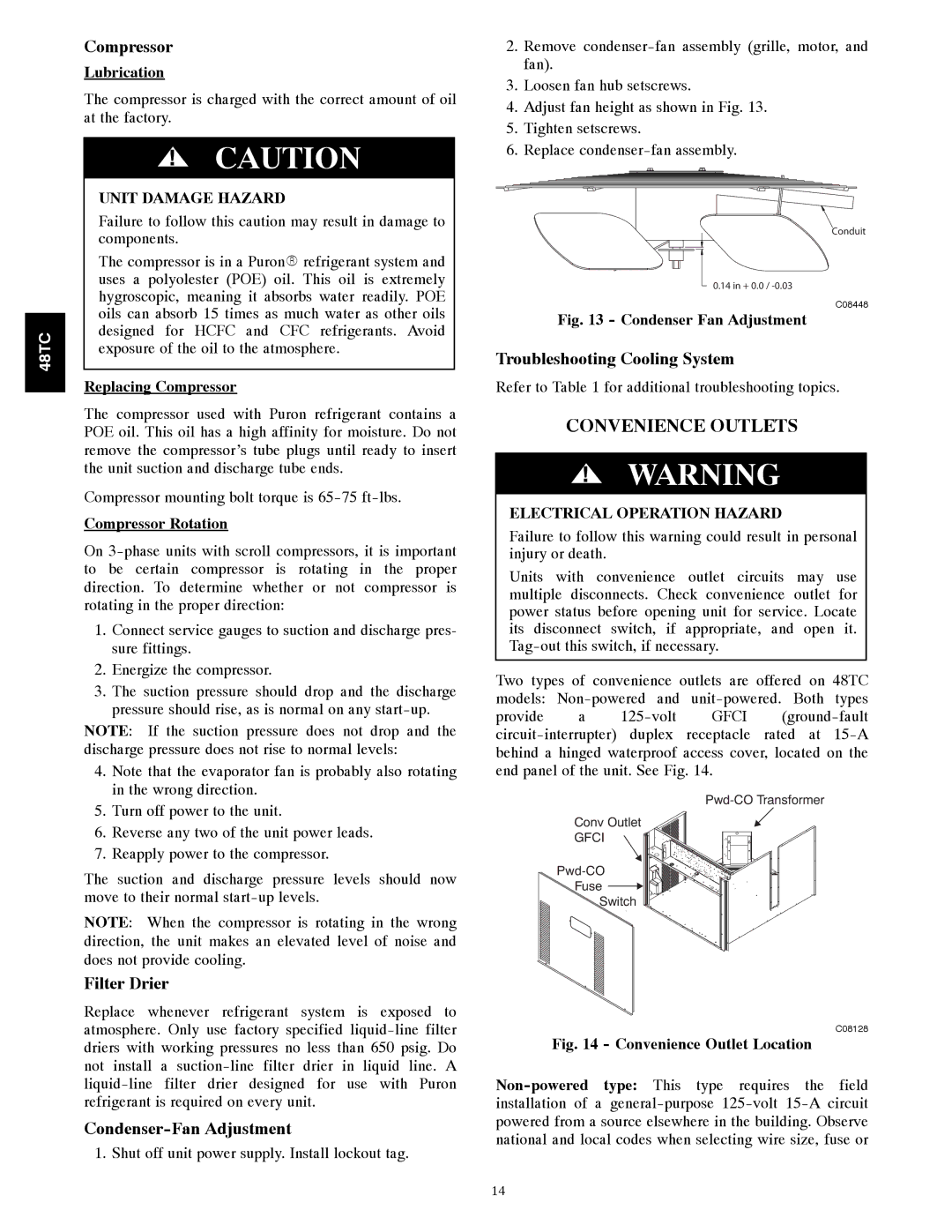
48TCA04---A12 specifications
The Carrier 48TCA04---A12 is a high-efficiency rooftop air conditioning unit designed for commercial and industrial applications. Known for its reliability and performance, this model features advanced technologies that cater to diverse climate control needs.One of the standout features of the Carrier 48TCA04---A12 is its excellent energy efficiency, which adheres to the stringent standards set by the U.S. Environmental Protection Agency. The unit utilizes a highly efficient scroll compressor combined with state-of-the-art heat exchanger technology, allowing it to operate with minimal energy consumption while providing powerful cooling capabilities.
The unit comes equipped with a robust and durable design, built to withstand various environmental conditions. Its weather-resistant cabinet is constructed from high-quality materials, ensuring long-lasting performance even in harsh climates. Additionally, the unit features a galvanized steel structure with a powder-coated finish, further enhancing its resistance to corrosion and wear.
In terms of technologies, the Carrier 48TCA04---A12 incorporates advanced controls that promote optimal performance. The unit supports Carrier's smart connectivity options, facilitating remote monitoring and adjustments via smart devices. This feature ensures convenient energy management and allows maintenance teams to access performance data, leading to proactive service interventions.
Another important characteristic of this unit is its quiet operation. The design includes sound-reducing insulation and a well-engineered airflow system, minimizing noise levels to create a more comfortable indoor environment. This is particularly important for commercial spaces such as offices and retail environments, where a tranquil atmosphere is critical for customer satisfaction and productivity.
The Carrier 48TCA04---A12 also offers diverse application flexibility, making it suitable for various locations, from small retail stores to large warehouses. With several tonnage options available, users can select a model that perfectly aligns with their specific cooling needs. Additionally, the unit can be easily integrated with existing HVAC systems, providing a seamless solution for upgrading or retrofitting older installations.
To sum up, the Carrier 48TCA04---A12 rooftop air conditioning unit stands out due to its exceptional energy efficiency, durable construction, advanced technology, and quiet operation, making it a reliable choice for commercial and industrial cooling solutions. Its flexibility and smart technology integrations ensure that it meets a wide range of climate control requirements effectively.

