White Rodgers 1F90W-51 Replacement Installation, Remove Old Thermostat, Attach Subbase To Wall

Models: 1F90W-51

1 8
Download 8 pages 19.13 Kb
Page 3
Image 3
REPLACEMENT INSTALLATION

REPLACEMENT INSTALLATION

REMOVE OLD THERMOSTAT

1.Shut off electricity at the main fuse box until installa- tion is complete. Verify power is off with a voltmeter.

2.Remove the front cover of the old thermostat. With wires still attached, remove wall plate from the wall.

3.If the old thermostat has a wall mounting plate, remove the thermostat and the wall mounting plate as an assembly.

4.FOR HEATING ONLY SYSTEMS — Disconnect the two wires from the old thermostat. Skip steps 5 through 7 below and proceed to ATTACH SUBBASE TO WALL.

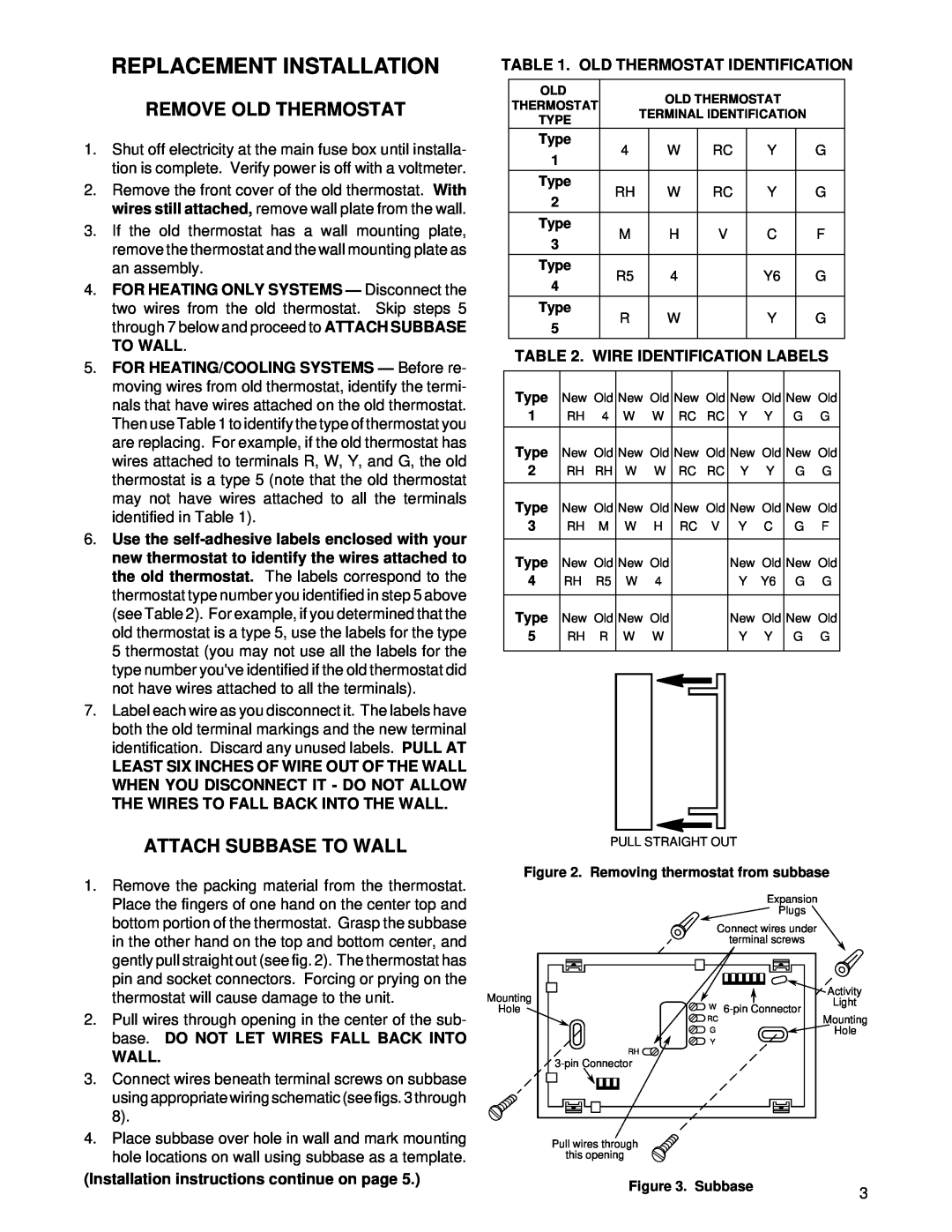
5.FOR HEATING/COOLING SYSTEMS — Before re- moving wires from old thermostat, identify the termi- nals that have wires attached on the old thermostat. Then use Table 1 to identify the type of thermostat you are replacing. For example, if the old thermostat has wires attached to terminals R, W, Y, and G, the old thermostat is a type 5 (note that the old thermostat may not have wires attached to all the terminals identified in Table 1).

6.Use the self-adhesive labels enclosed with your new thermostat to identify the wires attached to the old thermostat. The labels correspond to the thermostat type number you identified in step 5 above (see Table 2). For example, if you determined that the old thermostat is a type 5, use the labels for the type 5 thermostat (you may not use all the labels for the type number you've identified if the old thermostat did not have wires attached to all the terminals).

7.Label each wire as you disconnect it. The labels have both the old terminal markings and the new terminal identification. Discard any unused labels. PULL AT

LEAST SIX INCHES OF WIRE OUT OF THE WALL WHEN YOU DISCONNECT IT - DO NOT ALLOW THE WIRES TO FALL BACK INTO THE WALL.

TABLE 1. OLD THERMOSTAT IDENTIFICATION


OLD


OLD THERMOSTAT


THERMOSTAT


TERMINAL IDENTIFICATION


TYPE


Type


4


W


RC


Y


G


1


Type


RH


W


RC


Y


G


2


Type


M


H


V


C


F


3


Type


R5


4


Y6


G


4


Type


R


W


Y


G


5


TABLE 2. WIRE IDENTIFICATION LABELS


Type

New Old

New Old

New Old

New Old

New Old


1


RH 4

W W

RC RC

Y Y

G G


Type

New Old

New Old

New Old

New Old

New Old


2


RH RH

W


W

RC

RC

Y

Y

G

G


Type

New Old

New Old

New Old

New Old

New Old


3


RH M

W H

RC V

Y C

G F


Type


New Old

New Old


New Old

New Old


4


RH R5

W

4


Y

Y6

G

G


Type


New Old

New Old


New Old

New Old


5


RH R

W


W


Y

Y

G

G


ATTACH SUBBASE TO WALL

1.Remove the packing material from the thermostat. Place the fingers of one hand on the center top and bottom portion of the thermostat. Grasp the subbase in the other hand on the top and bottom center, and gently pull straight out (see fig. 2). The thermostat has pin and socket connectors. Forcing or prying on the thermostat will cause damage to the unit.

2.Pull wires through opening in the center of the sub- base. DO NOT LET WIRES FALL BACK INTO

WALL.

3.Connect wires beneath terminal screws on subbase using appropriate wiring schematic (see figs. 3 through 8).

4.Place subbase over hole in wall and mark mounting hole locations on wall using subbase as a template.

(Installation instructions continue on page 5.)

PULL STRAIGHT OUT

Figure 2. Removing thermostat from subbase

Expansion

Plugs

Connect wires under

terminal screws

Mounting


Activity

W


Light

Hole

6-pin Connector

Mounting


RC


G


Hole


Y


RH


3-pin Connector


Pull wires through

this opening

Figure 3. Subbase

3


Page 3
Image 3
White Rodgers 1F90W-51 installation instructions Replacement Installation, Remove Old Thermostat, Attach Subbase To Wall