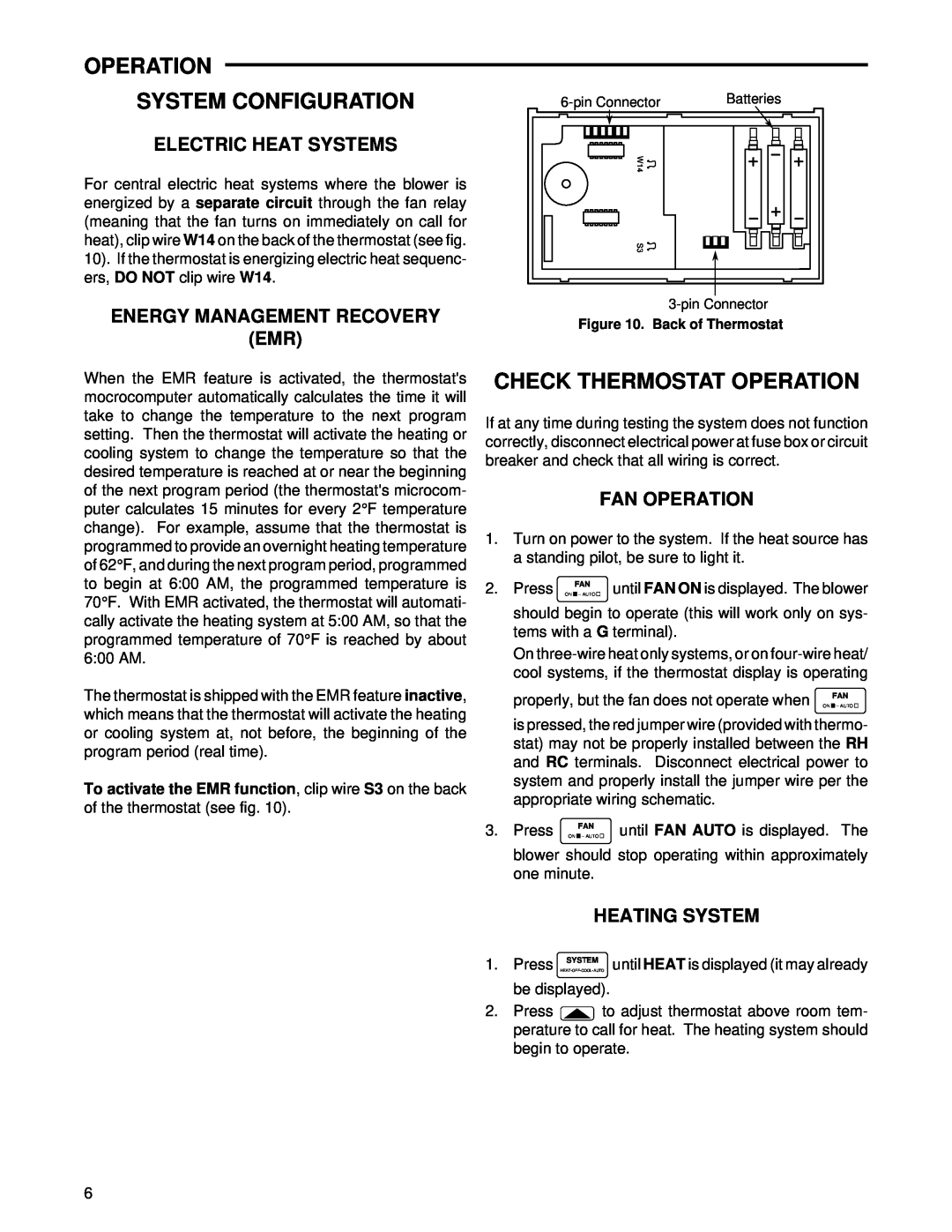
1F90W-51 specifications
The White Rodgers 1F90W-51 is a sophisticated thermostat designed for modern heating and cooling systems, offering homeowners a blend of convenience, energy efficiency, and advanced technology. This programmable thermostat is well-regarded for its user-friendly features and ease of installation, making it a popular choice among DIY enthusiasts and professionals alike.One of the standout features of the White Rodgers 1F90W-51 is its ability to provide precise temperature control. It supports a 7-day programming schedule, allowing users to set different temperatures for each day of the week, maximizing comfort while minimizing energy usage. This feature is particularly beneficial for families with varying schedules, enabling them to maintain optimal home temperatures when they are present and reduce heating or cooling when the house is empty.
The 1F90W-51 incorporates advanced technology that allows for compatibility with a wide range of HVAC systems, including conventional heating and cooling setups, heat pumps, and even multi-stage systems. The thermostat's digital display makes it easy for users to read and adjust settings, while its intuitive interface simplifies programming and operation.
In terms of efficiency, the White Rodgers 1F90W-51 is designed to help homeowners save on energy bills. By allowing for precise temperature adjustments and programmable schedules, it encourages users to optimize their heating and cooling usage. This not only protects the environment by reducing energy consumption but also translates to cost savings over time.
Another notable characteristic of the 1F90W-51 is its built-in temperature hold feature, which allows users to override the programmed settings temporarily. This is useful for occasions when unexpected changes in schedule may require a quick adjustment without the need to reprogram the entire unit.
In addition to functionality, the White Rodgers 1F90W-51 boasts a sleek design that blends seamlessly into any home décor. Its compact size and classic appearance allow it to fit well in various locations throughout the house.
Overall, the White Rodgers 1F90W-51 is a reliable and feature-rich thermostat that provides users with the tools needed to enhance their home comfort while remaining conscious of energy consumption. Its combination of programmability, compatibility, and user-friendly design makes it a top choice for those seeking an efficient and effective climate control solution.