WIRING DIAGRAMS
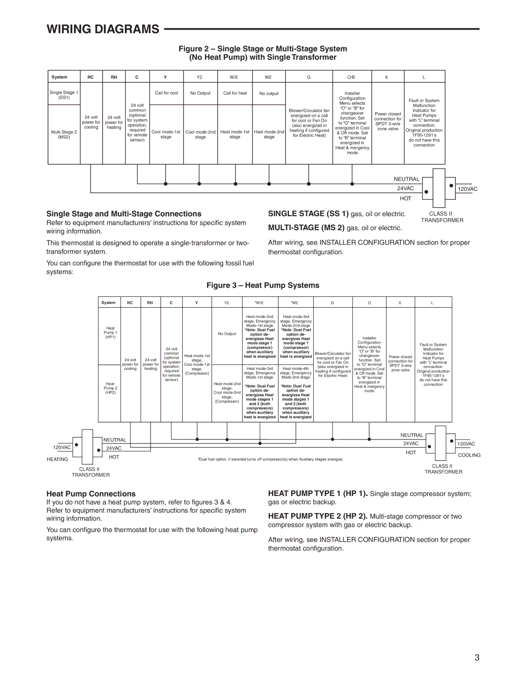
Figure 2 – Single Stage or Multi-Stage System
(No Heat Pump) with Single Transformer
System | RC | RH | C | Y | Y2 | W/E | W2 | G | O/B | 6 | L | |
|
|
|
|
|
|
|
|
|
|
|
| |
Single Stage 1 |
|
|
| Call for cool | No Output | Call for heat | No output |
| Installer |
|
| |
(SS1) |
|
|
|
|
|
|
|
| Configuration |
| Fault or System | |
|
|
| 24 volt |
|
|
|
|
| Menu selects |
| ||
|
|
|
|
|
|
|
|
| Malfunction | |||
|
|
|
|
|
|
|
| “O” or “B” for |
| |||
|
|
| common |
|
|
|
| Blower/Circulator fan |
| Indicator for | ||
|
|
|
|
|
|
| changeover | Power closed | ||||
| 24 volt | 24 volt | (optional |
|
|
|
| energized on a call | Heat Pumps | |||
| for system |
|
|
|
| for cool or Fan On | function. Set | connection for | with “L” terminal | |||
| power for | power for |
|
|
|
| to “O” terminal | SPDT | ||||
| cooling | heating | operation, |
|
|
|
| (also energized in | energized in Cool | connection. | ||
Multi Stage 2 | required | Cool | Cool | Heat | Heat | heating if configured | zone valve | Original production | ||||
|
| & Off mode. Set | ||||||||||
|
| for remote | for Electric Heat) |
| ||||||||
(MS2) |
|
| stage | stage | stage | stage | to “B” terminal |
| ||||
|
| sensor) |
|
| do not have this | |||||||
|
|
|
|
|
|
|
| energized in |
| |||
|
|
|
|
|
|
|
|
|
| connection | ||
|
|
|
|
|
|
|
|
| Heat & mergency |
| ||
|
|
|
|
|
|
|
|
|
|
| ||
|
|
|
|
|
|
|
|
| mode |
|
| |
|
|
|
|
|
|
|
|
|
|
|
|
|
| NEUTRAL |
|
|
|
|
|
|
|
|
|
|
|
|
|
| |
|
| 24VAC |
|
|
|
|
|
|
|
|
|
|
|
| 120VAC | ||
|
| HOT |
|
|
|
|
|
|
|
|
|
|
|
|
|
| |
Single Stage and | SINGLE STAGE (SS 1) gas, oil or electric. |
|
|
|
|
| ||
| CLASS II | |||||||
Refer to equipment manufacturers’ instructions for specific system | TRANSFORMER | |||||||
wiring information. |
|
|
|
|
|
| ||
|
|
|
|
|
|
| ||
This thermostat is designed to operate a | After wiring, see INSTALLER CONFIGURATION section for proper | |||||||
transformer system. | thermostat configuration. |
|
|
|
|
|
| |
You can configure the thermostat for use with the following fossil fuel systems:
Figure 3 – Heat Pump Systems
System | RC | RH | C | Y | Y2 | *W/E | *W2 | G | O | 6 | L |
|
|
|
|
|
|
|
|
|
|
|
|
|
|
|
|
|
| Heat | Heat |
|
|
|
|
|
|
|
|
|
| stage, Emergency | stage, Emergency |
|
|
|
|
Heat |
|
|
|
|
|
|
|
|
| ||
|
|
|
|
| *Note: Dual Fuel | *Note: Dual Fuel |
|
|
|
| |
Pump 1 |
|
|
|
| No Output |
|
|
|
| ||
|
|
|
| option de- | option de- |
|
|
|
| ||
(HP1) |
|
|
|
|
| Installer |
|
| |||
|
|
|
|
| energizes Heat | energizes Heat |
|
|
| ||
|
|
|
|
|
| mode stage 1 | mode stage 1 |
| Configuration |
| Fault or System |
|
|
| 24 volt |
|
| (compressor) | (compressor) |
| Menu selects |
| |
|
|
|
|
|
|
| Malfunction | ||||
|
|
|
|
| when auxiliary | when auxiliary |
| “O” or “B” for |
| ||
|
|
| common |
|
| Blower/Circulator fan |
| Indicator for | |||
|
|
| Heat |
| heat is energized | heat is energized | changeover | Power closed | |||
| 24 volt | 24 volt | (optional | stage, |
|
|
| energized on a call | function. Set | connection for | Heat Pumps |
| for system |
|
|
| for cool or Fan On | with “L” terminal | |||||
| power for | power for | Cool |
|
|
| to “O” terminal | SPDT | |||
| operation, |
| Heat | Heat | (also energized in | connection. | |||||
| cooling | heating | stage, |
| energized in Cool | ||||||
| required |
| heating if configured | zone valve | Original production | ||||||
|
|
| (Compressor) |
| stage, Emergency | stage, Emergency | & Off mode. Set |
| |||
|
|
| for remote |
|
| for Electric Heat) | to “B” terminal |
| |||
|
|
| sensor) |
|
|
|
| do not have this | |||
Heat |
|
|
| Heat |
|
|
| energized in |
| ||
|
|
|
| *Note: Dual Fuel | *Note: Dual Fuel |
|
| connection | |||
|
|
|
|
| Heat & mergency |
| |||||
Pump 2 |
|
|
|
| stage, |
|
|
| |||
|
|
|
| option de- | option de- |
| mode |
|
| ||
(HP2) |
|
|
|
| Cool |
|
|
| |||
|
|
|
| energizes Heat | energizes Heat |
|
|
|
| ||
|
|
|
|
| stage, |
|
|
|
| ||
|
|
|
|
| mode stages 1 | mode stages 1 |
|
|
|
| |
|
|
|
|
| (Compressor) |
|
|
|
| ||
|
|
|
|
| and 2 (both | and 2 (both |
|
|
|
| |
|
|
|
|
|
|
|
|
|
| ||
|
|
|
|
|
| compressors) | compressors) |
|
|
|
|
|
|
|
|
|
| when auxiliary | when auxiliary |
|
|
|
|
|
|
|
|
|
| heat is energized | heat is energized |
|
|
|
|
|
|
|
|
|
|
|
|
|
|
|
|
|
|
|
|
|
| NEUTRAL | |
|
|
|
|
|
| ||
120VAC | 120VAC |
| 24VAC | ||||
|
|
|
| ||||
HEATING | HOT | ||||||
|
|
|
| ||||
|
|
|
| ||||
|
|
|
|
| |||
|
|
|
|
| |||
|
| CLASS II | |||||
|
| TRANSFORMER | |||||
NEUTRAL |
|
|
|
|
|
|
|
|
|
|
|
| |
24VAC |
|
|
|
|
|
|
|
|
|
| 120VAC | ||
HOT |
|
|
|
|
|
|
|
|
|
| COOLING | ||
|
|
|
| |||
*Dual fuel option, if selected turns off compressor(s) when Auxiliary stages energize. |
|
|
|
| ||
|
|
|
|
|
| |
|
| CLASS II | ||||
| TRANSFORMER | |||||
Heat Pump Connections
If you do not have a heat pump system, refer to figures 3 & 4. Refer to equipment manufacturers’ instructions for specific system wiring information.
You can configure the thermostat for use with the following heat pump systems.
HEAT PUMP TYPE 1 (HP 1). Single stage compressor system; gas or electric backup.
HEAT PUMP TYPE 2 (HP 2).
After wiring, see INSTALLER CONFIGURATION section for proper thermostat configuration.
3