BRANCHEMENTS

Tous les branchements doivent être conformes aux codes et règlements électriques locaux et nationaux.

Brancher selon les schémas fournis par le fabricant de l’équipement. Si aucun n’est fourni, les schémas suivants représentent une installation typique.

Commandes avec un circuit (deux bornes)

Limite de basse température

Commande de

Commande de

pression élevée

température

(si utilisée)


L1

Vers le

Lignecompresseur du moteur

L2 Remarque : Brancher L1 "SOUS TENSION" sur l'installation en 120 V

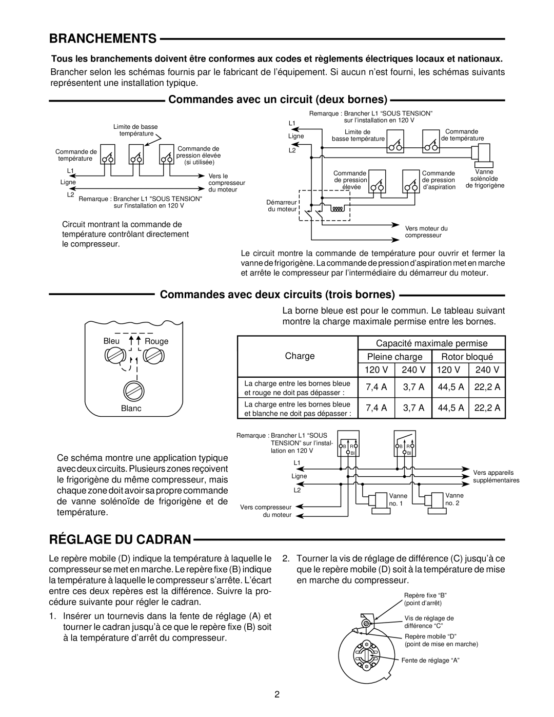
Circuit montrant la commande de température contrôlant directement le compresseur.

Remarque : Brancher L1 “SOUS TENSION”

L1

sur l’installation en 120 V


Ligne

Limite de

Commande

basse température

de température


L2


Commande

Commande

Vanne


de pression

de pression

solénoïde


élevée

d’aspiration

de frigorigène

Démarreur du moteur

Vers moteur du compresseur

Le circuit montre la commande de température pour ouvrir et fermer la vanne de frigorigène. La commande de pression d’aspiration met en marche et arrête le compresseur par l’intermédiaire du démarreur du moteur.

Commandes avec deux circuits (trois bornes)

Bleu Rouge

Blanc

La borne bleue est pour le commun. Le tableau suivant montre la charge maximale permise entre les bornes.


Capacité maximale permise

Charge

Pleine charge

Rotor bloqué


120 V

240 V

120 V

240 V


La charge entre les bornes bleue

7,4 A

3,7 A

44,5 A

22,2 A

et rouge ne doit pas dépasser :


La charge entre les bornes bleue

7,4 A

3,7 A

44,5 A

22,2 A

et blanche ne doit pas dépasser :


Ce schéma montre une application typique avec deux circuits. Plusieurs zones reçoivent le frigorigène du même compresseur, mais chaque zone doit avoir sa propre commande de vanne solénoïde de frigorigène et de température.

Remarque : Brancher L1 “SOUS

TENSION” sur l’instal-

B


R


lation en 120 V


W


Bl

L1

Ligne

L2

Vers compresseur du moteur

BR

W Bl

Vanne no. 1

Vers appareils supplémentaires

Vanne no. 2

RÉGLAGE DU CADRAN

Le repère mobile (D) indique la température à laquelle le compresseur se met en marche. Le repère fixe (B) indique la température à laquelle le compresseur s’arrête. L’écart entre ces deux repères est la différence. Suivre la pro- cédure suivante pour régler le cadran.

1.Insérer un tournevis dans la fente de réglage (A) et tourner le cadran jusqu’à ce que le repère fixe (B) soit à la température d’arrêt du compresseur.

2.Tourner la vis de réglage de différence (C) jusqu’à ce que le repère mobile (D) soit à la température de mise en marche du compresseur.

Repère fixe “B” (point d’arrêt)

Vis de réglage de différence “C”

Repère mobile “D”

(point de mise en marche)

Fente de réglage “A”

2

Page 4
Image 4
White Rodgers 241-2, 1609 installation instructions Branchements, Réglage DU Cadran, Commandes avec un circuit deux bornes

1609, 241-2 specifications

The White Rodgers 241-2,1609 is a sophisticated thermostat designed for residential heating and cooling systems. Known for its reliability and user-friendly interface, this model stands out in the realm of climate control technologies.

One of the main features of the White Rodgers 241-2,1609 is its easy-to-read LCD display, which provides clear visibility of the temperature settings and system status. This feature enhances usability, allowing homeowners to monitor and adjust their indoor climate effortlessly. The thermostat is equipped with intuitive buttons that enable quick changes to settings, facilitating a seamless user experience.

Technologically, the White Rodgers 241-2,1609 boasts advanced temperature control features, including programmable settings that allow users to establish heating and cooling schedules. This programmable functionality not only enhances comfort but also aids in energy savings by allowing homeowners to optimize their HVAC systems according to their daily routines. The thermostat can be programmed for different days of the week and can accommodate multiple daily settings, making it both versatile and practical.

The 241-2,1609 supports both heating and cooling systems, including conventional gas, oil, or electric systems, as well as heat pumps. This broad compatibility ensures that homeowners can integrate the thermostat into a variety of existing HVAC setups, making it a flexible choice for many households.

Another characteristic of this thermostat is its adaptive intelligent technology. This feature enables the thermostat to learn household patterns and adjust settings accordingly, providing enhanced energy efficiency. For example, if the system detects that occupants typically leave the house during certain hours, it can automatically adjust the temperature to conserve energy while maintaining comfort when they return.

Installation of the White Rodgers 241-2,1609 is straightforward, thanks to its user-centric design. The thermostat typically comes with an easy-to-follow installation guide, allowing homeowners to set it up without professional assistance, provided they have basic knowledge of HVAC systems.

Durability is another hallmark of this model. Built with high-quality materials, the White Rodgers 241-2,1609 is designed to withstand everyday use while ensuring long-lasting performance. Moreover, the thermostat features a user-replaceable battery, minimizing maintenance inconveniences and enhancing longevity.

In summary, the White Rodgers 241-2,1609 embodies a blend of functionality, user-friendly design, and advanced technologies, catering to homeowners who seek an efficient and reliable solution for managing their indoor climate. Its programmable features, compatibility with various systems, and intelligent technology make it a noteworthy choice in the domain of home climate control.