50A55-743 specifications
The White Rodgers 50A55-743 is a versatile and highly efficient universal gas furnace control board widely recognized for its reliability and advanced features. Designed to enhance the performance and safety of heating systems, it caters to both residential and commercial applications, making it a preferred choice for HVAC professionals and homeowners alike.One of the standout features of the 50A55-743 is its universal compatibility. It is designed to work with a variety of gas furnaces from different manufacturers, significantly simplifying the installation and replacement process. This feature saves time and reduces overhead costs for technicians, as they no longer have to stock multiple control boards for various furnace models.
The control board operates using advanced microprocessor technology, which ensures precise control over the heating cycle. This precision translates into optimal comfort for the occupants and can lead to significant energy savings. The board is capable of monitoring and adjusting the heating process in real-time, adapting to the specific demands of the environment.
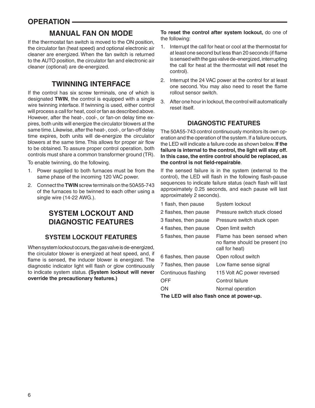
Another important characteristic of the White Rodgers 50A55-743 is its built-in diagnostics. The board features LED indicators that provide real-time feedback on the furnace's operational status. These diagnostic lights help technicians quickly identify issues, minimizing downtime and improving service efficiency. Together with its user-friendly design, these features make troubleshooting a more straightforward process.
Safety is a paramount consideration in HVAC systems, and the 50A55-743 excels in this aspect as well. It includes multiple safety features such as flame proving, limit control, and lockout capabilities, which enhance the operational integrity of the furnace. These features help to prevent unsafe operating conditions, providing peace of mind for users.
The control board can also work with variable speed blower motors, allowing it to effectively manage airflow and heating output, leading to improved efficiency and comfort levels. Its adaptability to different configurations makes it a powerful component in modern HVAC systems.
In conclusion, the White Rodgers 50A55-743 stands out as a leading control board in the HVAC industry. With its universal compatibility, advanced microprocessor technology, built-in diagnostics, and robust safety features, it represents a significant advancement in furnace control, enhancing reliability, efficiency, and overall user satisfaction. This makes it an excellent choice for anyone looking to upgrade their heating system.