PREINSTALLATION

Not to Exceed 20

Air Flow

Furnace

Air Flow


Opening


Electronic


Air Cleaner


Opening

Furnace

Electronic

Transition Section

Air Cleaner

(if Needed)


Figure 3

LOCATING THE AIR FILTER

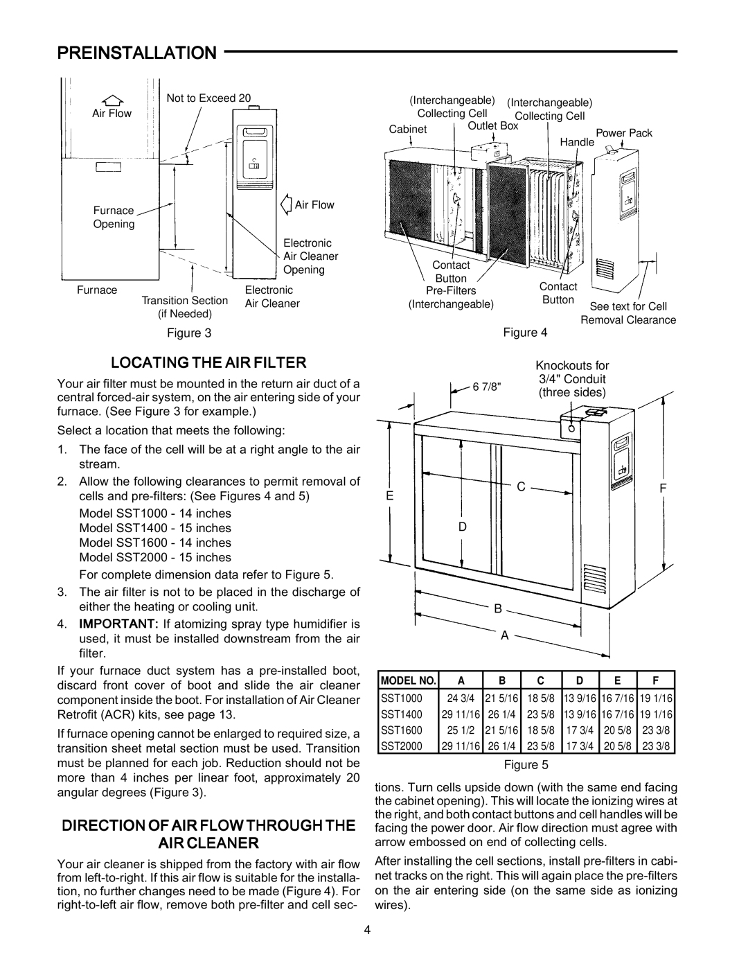
Your air filter must be mounted in the return air duct of a central forced-air system, on the air entering side of your furnace. (See Figure 3 for example.)

Select a location that meets the following:

(Interchangeable)

(Interchangeable)

Collecting Cell

Collecting Cell

Cabinet

Outlet Box

Power Pack


Handle

Contact


Button

Contact


Pre-Filters


Button


(Interchangeable)

See text for Cell


Figure 4

Removal Clearance


Knockouts for

6 7/8"

3/4" Conduit

(three sides)


1.

The face of the cell will be at a right angle to the air


stream.

2.

Allow the following clearances to permit removal of


cells and pre-filters: (See Figures 4 and 5)


Model SST1000 - 14 inches

E

CF


Model SST1400 - 15 inches


Model SST1600 - 14 inches


Model SST2000 - 15 inches


For complete dimension data refer to Figure 5.

3.

The air filter is not to be placed in the discharge of


either the heating or cooling unit.

4.

IMPORTANT: If atomizing spray type humidifier is


used, it must be installed downstream from the air


filter.

If your furnace duct system has a pre-installed boot, discard front cover of boot and slide the air cleaner component inside the boot. For installation of Air Cleaner Retrofit (ACR) kits, see page 13.

If furnace opening cannot be enlarged to required size, a transition sheet metal section must be used. Transition must be planned for each job. Reduction should not be more than 4 inches per linear foot, approximately 20 angular degrees (Figure 3).

DIRECTION OF AIR FLOW THROUGH THE

AIR CLEANER

Your air cleaner is shipped from the factory with air flow from left-to-right. If this air flow is suitable for the installa- tion, no further changes need to be made (Figure 4). For right-to-left air flow, remove both pre-filter and cell sec-

D

B

A

MODEL NO.

A

B

C

D

E

F

SST1000

24 3/4

21 5/16

18 5/8

13 9/16

16 7/16

19 1/16

SST1400

29 11/16

26 1/4

23 5/8

13 9/16

16 7/16

19 1/16

SST1600

25 1/2

21 5/16

18 5/8

17 3/4

20 5/8

23 3/8

SST2000

29 11/16

26 1/4

23 5/8

17 3/4

20 5/8

23 3/8

Figure 5

tions. Turn cells upside down (with the same end facing the cabinet opening). This will locate the ionizing wires at the right, and both contact buttons and cell handles will be facing the power door. Air flow direction must agree with arrow embossed on end of collecting cells.

After installing the cell sections, install pre-filters in cabi- net tracks on the right. This will again place the pre-filters on the air entering side (on the same side as ionizing wires).

4

Page 4
Image 4
White Rodgers SST1400, SST2000, SST1600 Preinstallation, Locating the AIR Filter, Direction of AIR Flow Through AIR Cleaner

SST1600, SST2000, SST1400 specifications

White Rodgers, a renowned name in the HVAC industry, has made significant strides in programmable thermostat technology with its SST series, particularly the SST2000, SST1400, and SST1600 models. These thermostats are designed to enhance comfort while maximizing energy efficiency, making them essential tools for both residential and commercial applications.

The SST2000 model stands out with its user-friendly interface, offering a large, backlit display that simplifies programming and adjustments. One of its key features is the four-day programmable schedule, allowing users to customize settings according to their lifestyle. This flexibility ensures optimal heating and cooling, reducing energy costs. The SST2000 also incorporates predictive recovery technology, enabling the system to achieve the desired temperature by the scheduled time, ensuring a comfortable environment without wasting energy.

Moving on to the SST1400, this model is designed for simplicity while maintaining essential programmable features. It also boasts an easy-to-read display and logical button layout for straightforward navigation. With flexible programming options, the SST1400 allows users to set a weekly schedule, accommodating different routines on weekdays and weekends. This model prioritizes energy savings and comfort, offering features like vacation mode, which minimizes energy use when the home is unoccupied.

The SST1600 model takes programmability to the next level with advanced features, including a touchscreen interface. Its smart technology allows for intuitive programming and real-time adjustments, making it suitable for tech-savvy users. The SST1600 can integrate with smart home systems, providing remote access and control via mobile applications. This ensures that homeowners can monitor and adjust their heating and cooling systems from anywhere, enhancing convenience and energy management.

All three models incorporate energy-saving strategies, such as adaptive recovery, which learns how long it takes for the HVAC system to reach the desired temperature, optimizing its performance without user intervention. The thermostats are also compatible with various heating and cooling systems, making them versatile options for diverse setups.

In summary, the White Rodgers SST2000, SST1400, and SST1600 offer distinct features that cater to a range of user preferences. From intuitive displays and programmable schedules to smart technology integration, these thermostats exemplify modern comforts while prioritizing energy efficiency, making them valuable additions to any home or business.