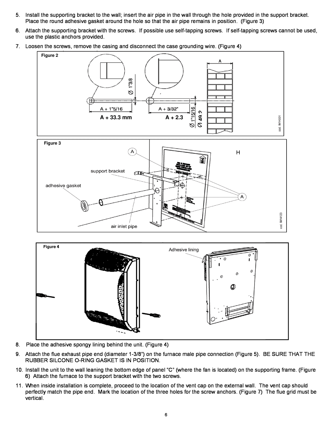
5.Install the supporting bracket to the wall; insert the air pipe in the wall through the hole provided in the support bracket. Place the round adhesive gasket around the hole so that the air pipe remains in position. (Figure 3)
6.Attach the supporting bracket with the screws. If possible use
7.Loosen the screws, remove the casing and disconnect the case grounding wire. (Figure 4)
Figure 2
A + 33.3 mm | A + 2.3 |
Figure 3
Ø 49.2
H
Figure 4
8.Place the adhesive spongy lining behind the unit. (Figure 4)
9.Attach the flue exhaust pipe end (diameter
10.Install the unit to the wall leaning the bottom edge of panel “C” (where the fan is located) on the supporting frame. (Figure
6)Attach the furnace to the support bracket with the two screws.
11.When inside installation is complete, proceed to the location of the vent cap on the external wall. The vent cap should perfectly match the pipe end. Mark the location of the three holes for the screw anchors. (Figure 7) The flue grid must be vertical.
6
