Troubleshooting Step 3
Point 5 (Z1)
Z1 is open and no ignition.
Check wiring and connections. If everything is okay, replace the switch.
Point 7 (M2)
M2 is closed and fan thermostat temperature is lower than 104 °F.
Check wiring and connections. If they are okay, replace the thermostat.
Step 4
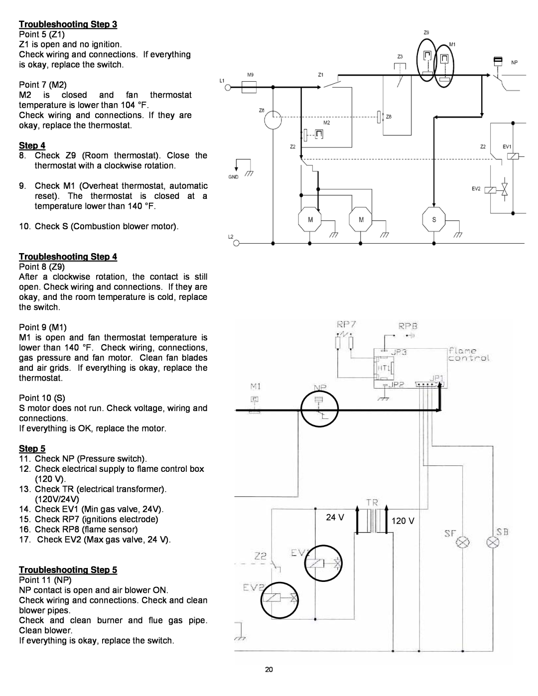
8.Check Z9 (Room thermostat). Close the thermostat with a clockwise rotation.
9.Check M1 (Overheat thermostat, automatic reset). The thermostat is closed at a temperature lower than 140 °F.
10.Check S (Combustion blower motor).
Troubleshooting Step 4
Point 8 (Z9)
After a clockwise rotation, the contact is still open. Check wiring and connections. If they are okay, and the room temperature is cold, replace the switch.
Point 9 (M1)
M1 is open and fan thermostat temperature is lower than 140 °F. Check wiring, connections, gas pressure and fan motor. Clean fan blades and air grids. If everything is okay, replace the thermostat.
Point 10 (S)
S motor does not run. Check voltage, wiring and connections.
If everything is OK, replace the motor.
Step 5
11.Check NP (Pressure switch).
12.Check electrical supply to flame control box (120 V).
13.Check TR (electrical transformer). (120V/24V)
14.Check EV1 (Min gas valve, 24V).
15.Check RP7 (ignitions electrode)
16.Check RP8 (flame sensor)
17.Check EV2 (Max gas valve, 24 V).
Troubleshooting Step 5
Point 11 (NP)
NP contact is open and air blower ON.
Check wiring and connections. Check and clean blower pipes.
Check and clean burner and flue gas pipe. Clean blower.
If everything is okay, replace the switch.
24 V | 120 V |
|
20