Figure 1
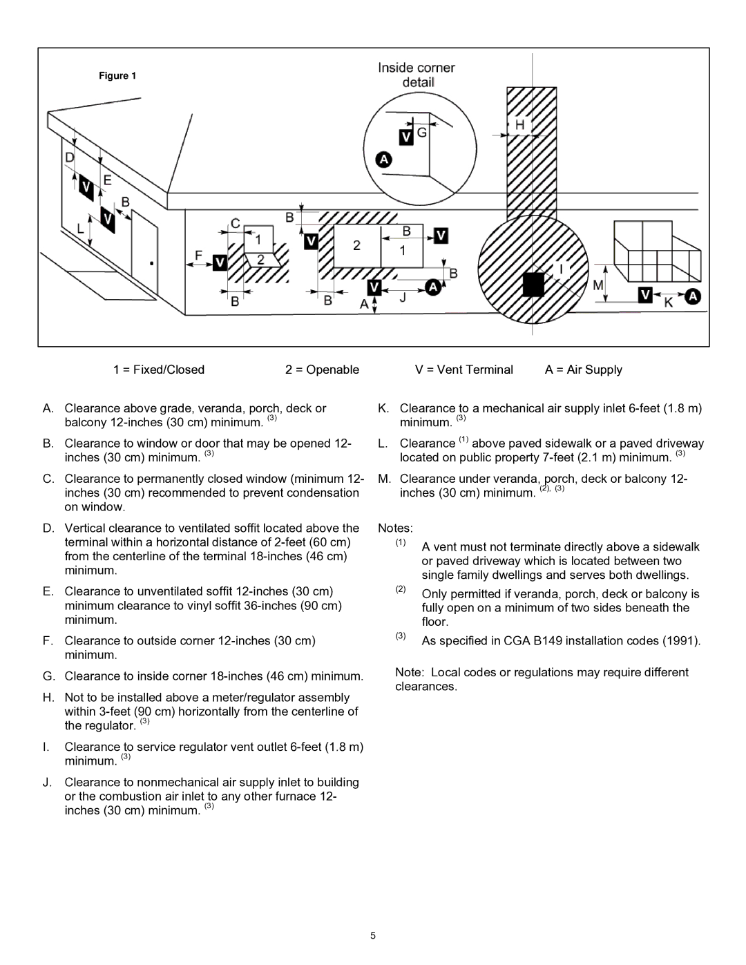
1 = Fixed/Closed | 2 = Openable | V = Vent Terminal | A = Air Supply |
A.Clearance above grade, veranda, porch, deck or balcony
B.Clearance to window or door that may be opened 12- inches (30 cm) minimum. (3)
C.Clearance to permanently closed window (minimum 12- inches (30 cm) recommended to prevent condensation on window.
K.Clearance to a mechanical air supply inlet
L.Clearance (1) above paved sidewalk or a paved driveway located on public property
M.Clearance under veranda, porch, deck or balcony 12- inches (30 cm) minimum. (2), (3)
D.Vertical clearance to ventilated soffit located above the terminal within a horizontal distance of
E.Clearance to unventilated soffit
F.Clearance to outside corner
Notes:
(1)A vent must not terminate directly above a sidewalk or paved driveway which is located between two single family dwellings and serves both dwellings.
(2)Only permitted if veranda, porch, deck or balcony is fully open on a minimum of two sides beneath the floor.
(3)As specified in CGA B149 installation codes (1991).
G.Clearance to inside corner
H.Not to be installed above a meter/regulator assembly within
I.Clearance to service regulator vent outlet
J.Clearance to nonmechanical air supply inlet to building or the combustion air inlet to any other furnace 12- inches (30 cm) minimum. (3)
Note: Local codes or regulations may require different clearances.
5