Resetting the STOP switch
1.Turn the switch in the direction of the arrow on the red button
Using the load ammeter
An ammeter on the control console is used to monitor the load on the spindle drive motor. It is connected into one of the three power lines which supply the main drive motor.
When the drive motor is ON and up to speed, and there is no tooling being used to drill, tap or bore a hole, the ammeter should read approximately 2.5 amps. If it is above this value there is a problem internally (such as lack of lubrication in the gear- boxes, bad bearings, etc.) which means you should turn off the machine and determine the cause of the excessive
Monitor the the ammeter during machining operations. The ammeter should stay below 9 amps or current draw during machining. You should adjust your spindle speed, feed rate and coolant use to maintain the full load current draw below the 9 amp value.
If you exceed 9 amps current draw a thermal limiter switch in the electrical control panel will trip. If this occurs, a licensed electrician should be used to locate and
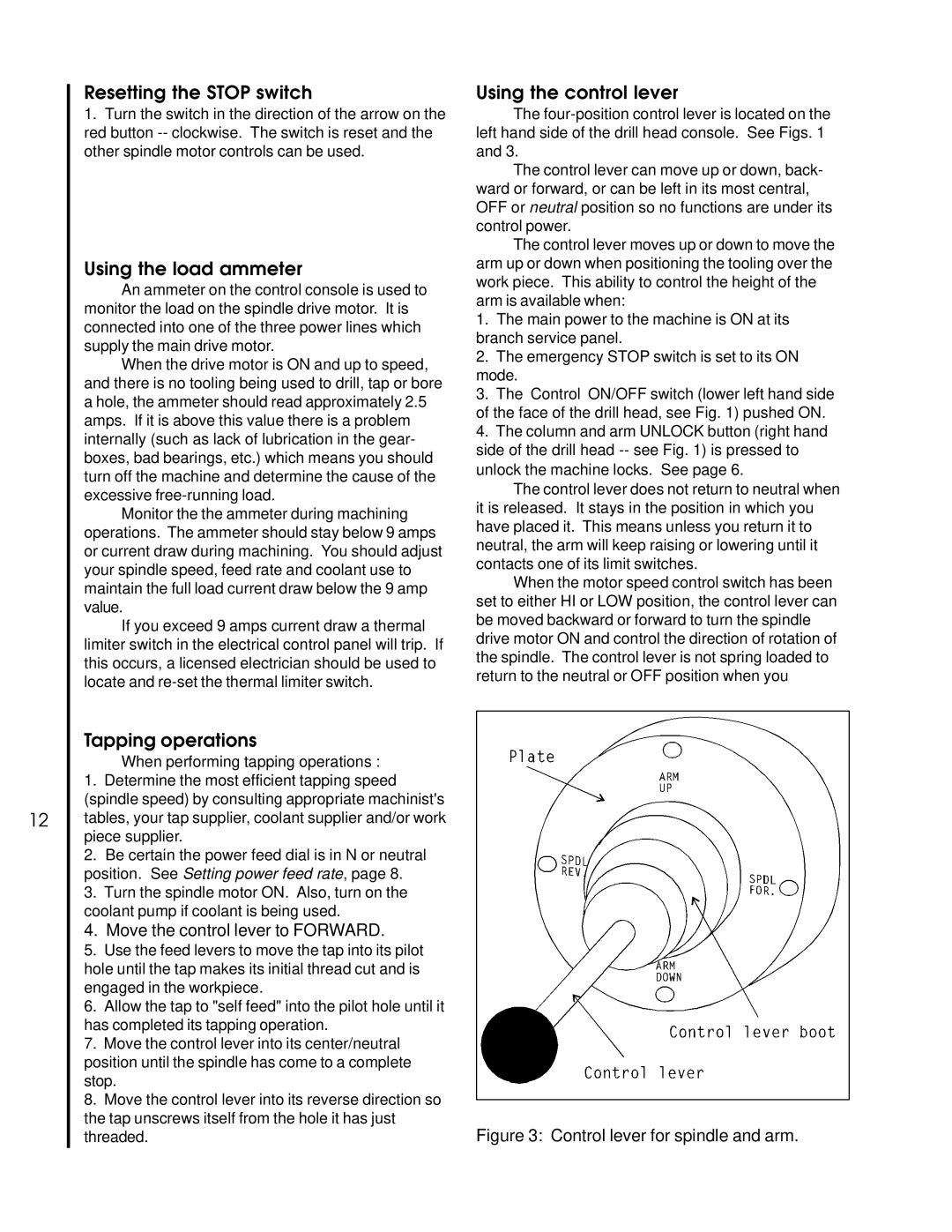
Using the control lever
The
The control lever can move up or down, back- ward or forward, or can be left in its most central, OFF or neutral position so no functions are under its control power.
The control lever moves up or down to move the arm up or down when positioning the tooling over the work piece. This ability to control the height of the arm is available when:
1.The main power to the machine is ON at its branch service panel.
2.The emergency STOP switch is set to its ON mode.
3.The Control ON/OFF switch (lower left hand side of the face of the drill head, see Fig. 1) pushed ON.
4.The column and arm UNLOCK button (right hand side of the drill head
The control lever does not return to neutral when it is released. It stays in the position in which you have placed it. This means unless you return it to neutral, the arm will keep raising or lowering until it contacts one of its limit switches.
When the motor speed control switch has been set to either HI or LOW position, the control lever can be moved backward or forward to turn the spindle drive motor ON and control the direction of rotation of the spindle. The control lever is not spring loaded to return to the neutral or OFF position when you
12
Tapping operations
When performing tapping operations :
1.Determine the most efficient tapping speed (spindle speed) by consulting appropriate machinist's tables, your tap supplier, coolant supplier and/or work piece supplier.
2.Be certain the power feed dial is in N or neutral position. See Setting power feed rate, page 8.
3.Turn the spindle motor ON. Also, turn on the coolant pump if coolant is being used.
4.Move the control lever to FORWARD.
5.Use the feed levers to move the tap into its pilot hole until the tap makes its initial thread cut and is engaged in the workpiece.
6.Allow the tap to "self feed" into the pilot hole until it has completed its tapping operation.
7.Move the control lever into its center/neutral position until the spindle has come to a complete stop.
8.Move the control lever into its reverse direction so the tap unscrews itself from the hole it has just
threaded. | Figure 3: Control lever for spindle and arm. |