Optional Equipment
Coolant System Installation
1.Remove the large reservoir cover plate from the
machine base. Tap
2.Insert the pump into the opening, utilize the screws from the small round cover plate to fasten the pump to the base.
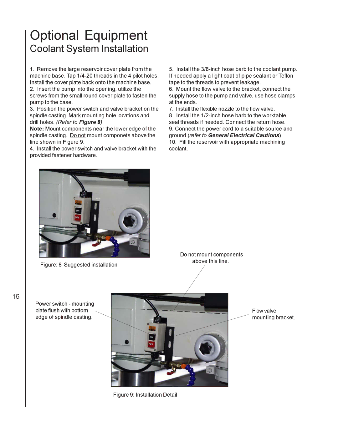
3.Position the power switch and valve bracket on the spindle casting. Mark mounting hole locations and drill holes. (Refer to Figure 8).
Note: Mount components near the lower edge of the spindle casting. Do not mount componets above the line shown in Figure 9.
4.Install the power switch and valve bracket with the provided fastener hardware.
5.Install the
6.Mount the flow valve to the bracket, connect the supply hose to the pump and valve, use hose clamps at the ends.
7.Install the flexible nozzle to the flow valve.
8.Install the
9.Connect the power cord to a suitable source and ground (refer to General Electrical Cautions).
10.Fill the reservoir with appropriate machining coolant.
16