20
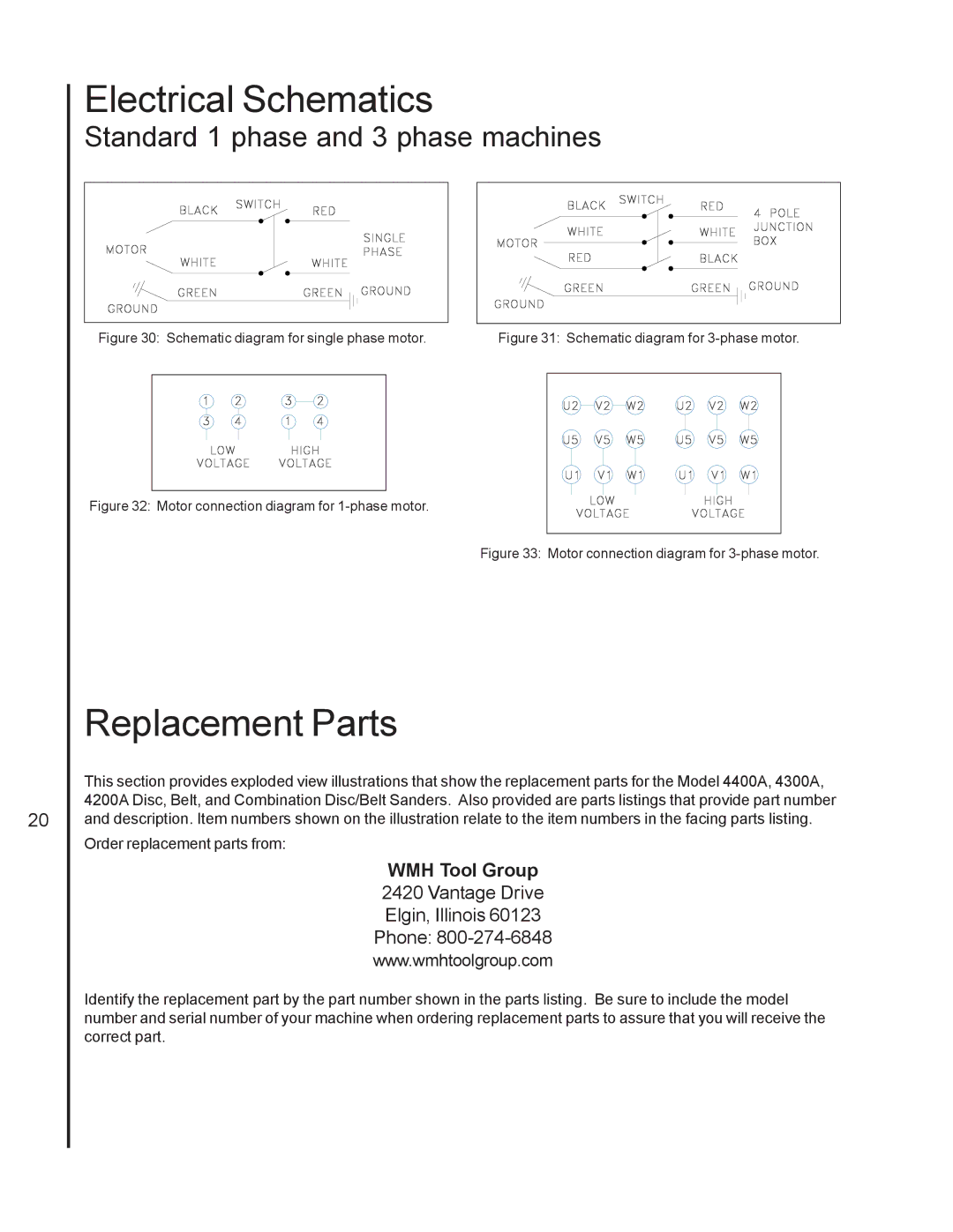
Electrical Schematics
Standard 1 phase and 3 phase machines
Figure 30: Schematic diagram for single phase motor. | Figure 31: Schematic diagram for | |||||||||||
|
|
|
|
|
|
|
|
|
|
|
|
|
|
|
|
|
|
|
|
|
|
|
|
|
|
|
|
|
|
|
|
|
|
|
|
|
|
|
|
|
|
|
|
|
|
|
|
|
|
|
|
|
|
|
|
|
|
|
|
|
|
|
|
|
|
|
|
|
|
|
|
|
|
|
|
|
|
|
|
|
|
|
|
|
|
|
|
|
|
|
Figure 32: Motor connection diagram for 1-phase motor.
Figure 33: Motor connection diagram for 3-phase motor.
Replacement Parts
This section provides exploded view illustrations that show the replacement parts for the Model 4400A, 4300A, 4200A Disc, Belt, and Combination Disc/Belt Sanders. Also provided are parts listings that provide part number and description. Item numbers shown on the illustration relate to the item numbers in the facing parts listing.
Order replacement parts from:
WMH Tool Group
2420 Vantage Drive
Elgin, Illinois 60123
Phone: 800-274-6848
www.wmhtoolgroup.com
Identify the replacement part by the part number shown in the parts listing. Be sure to include the model number and serial number of your machine when ordering replacement parts to assure that you will receive the correct part.
