1.Remove front blade guide by removing adjust- ment knob, spring, and shaft.
2.Remove the rear blade guide by removing its attachment screw
3.Install replacement blade guide in the rear guide location. Secure with attachment screw.
4.Install replacement blade guide in the front guide location. Install shaft into guide. Install spring and adjustment knob.
5.Adjust outermost blade guide using adjustment knob. Set the guide so it just contacts the side of the blade.
Replacement of Guide
Bearings (see figure 19)
1. Remove the cap screw from the blade guide bearing. Separate the bushing and cap screw from the bearing. Discard the bearing.
NOTE: There is a light press fit between the bearing and the bushing.
2.Install bushing in replacement bearing. Install cap screw through bushing and into guide support.
3.Turn the eccentric bushing in the guide support until the bearing contacts the blade.
Replacement of Blade Edge
Bearings (see figure 20)
1.Remove the capscrew from the blade edge bearing being replaced and discard the bearing.
2.Insert the capscrew into the new bearing.
3.Adjust blade edge guide bearings so they just contact the edge of the blade.
Adjustment | Guide Support |
Cap Screw |
|
Floating Block |
|
Cap Screw |
|
Blade Edge |
|
Bearing |
|
Figure 20: Blade Edge Bearing Replacement
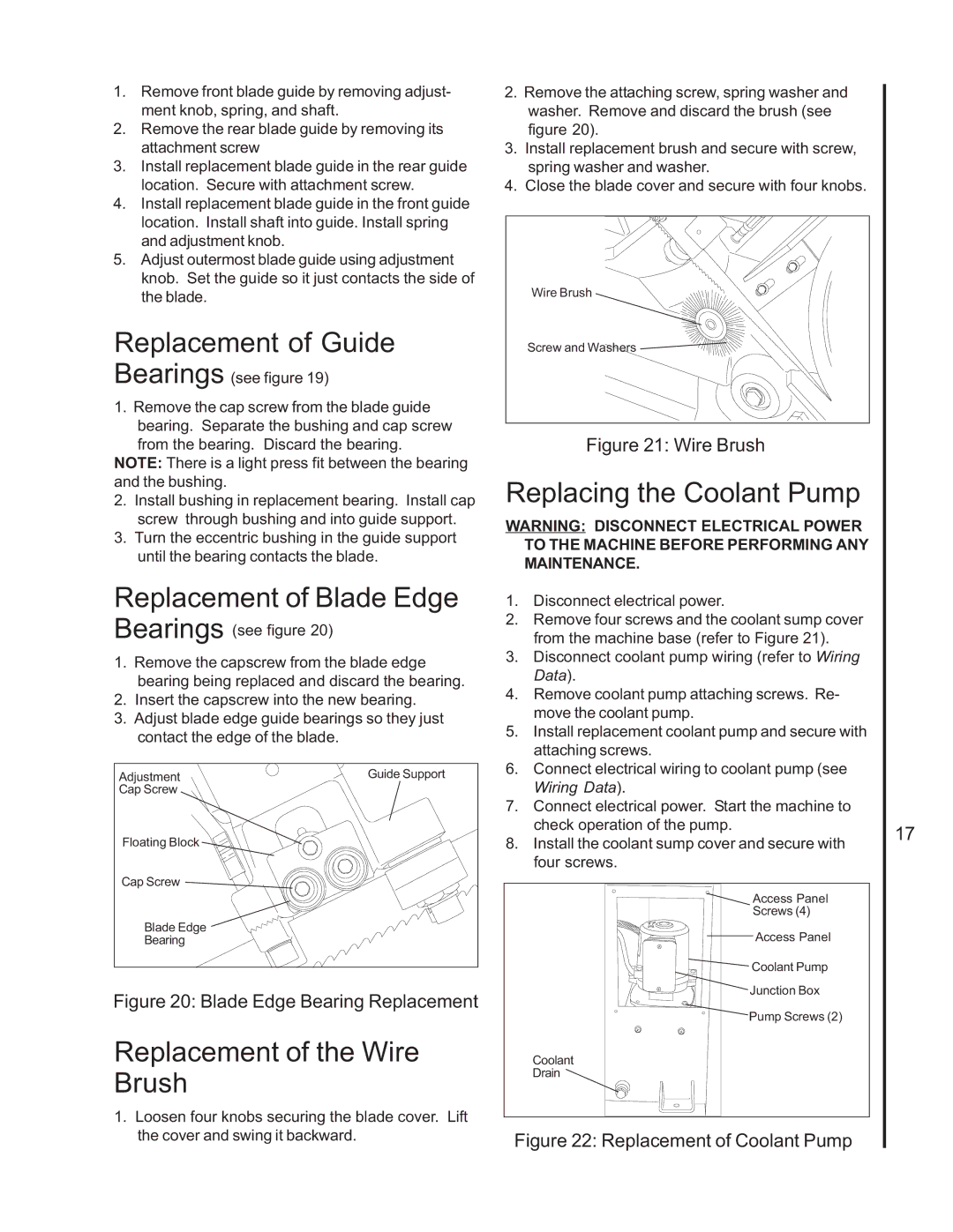
Replacement of the Wire Brush
1.Loosen four knobs securing the blade cover. Lift the cover and swing it backward.
2.Remove the attaching screw, spring washer and washer. Remove and discard the brush (see figure 20).
3.Install replacement brush and secure with screw, spring washer and washer.
4.Close the blade cover and secure with four knobs.
Wire Brush
Screw and Washers
Figure 21: Wire Brush
Replacing the Coolant Pump
WARNING: DISCONNECT ELECTRICAL POWER TO THE MACHINE BEFORE PERFORMING ANY MAINTENANCE.
1.Disconnect electrical power.
2.Remove four screws and the coolant sump cover from the machine base (refer to Figure 21).
3.Disconnect coolant pump wiring (refer to Wiring Data).
4.Remove coolant pump attaching screws. Re- move the coolant pump.
5.Install replacement coolant pump and secure with attaching screws.
6.Connect electrical wiring to coolant pump (see Wiring Data).
7.Connect electrical power. Start the machine to check operation of the pump.
8.Install the coolant sump cover and secure with four screws.
Access Panel
Screws (4)
Access Panel
Coolant Pump
Junction Box
Pump Screws (2)
Coolant
Drain
Figure 22: Replacement of Coolant Pump
17