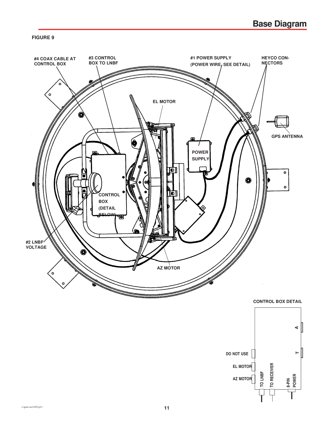
Winegard MV-1111, MV-2222 manual Base Diagram

Models: MV-1111 MV-2222

1 12
Download 12 pages 53.72 Kb
Page 11
Image 11
Base Diagram

Base Diagram

FIGURE 9

#4 COAX CABLE AT CONTROL BOX

#2 LNBF VOLTAGE

#3 CONTROL

#1 POWER SUPPLY

BOX TO LNBF

(POWER WIRE, SEE DETAIL)


EL MOTOR

POWER

SUPPLY

CONTROL BOX (DETAIL BELOW)

AZ MOTOR

DO NOT USE

EL MOTOR

AZ MOTOR

HEYCO CON-

NECTORS

GPS ANTENNA

CONTROL BOX DETAIL

A


T

TOLNBF

TORECEIVER

8-PIN POWER


s:\part-no\1021p11

11


Page 11
Image 11
Winegard MV-1111, MV-2222 manual Base Diagram

FAQ

What is included in the base diagram?

The base diagram includes the COAX cable at the control box, LNBF voltage, power supply, and control box details.

How do I connect the power wire to the control box?

Refer to the detailed diagram provided for connecting the power wire to the control box.

What are the Heyco connectors used for?

The Heyco connectors are used for connecting the GPS antenna and control box details.