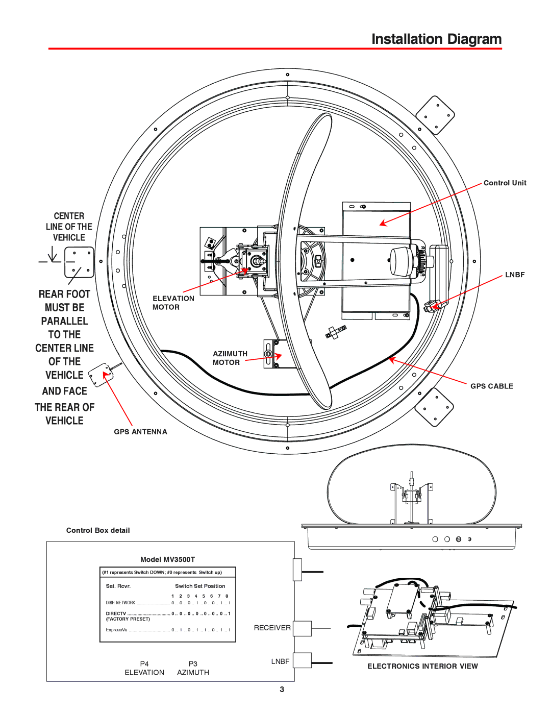
MVT-35B, MVT-35W, WI3535T, MV3500T, MV3535T specifications
The Winegard MV3500T, MV3535T, MVT-35B, MVT-35W, and WI3535T are some of the most advanced and versatile over-the-air TV antennas available today. Designed for both urban and rural environments, these antennas offer exceptional reception capabilities and a range of features that cater to diverse viewing needs.The MV3500T is a compact, high-performance antenna that integrates advanced technology to ensure reliable reception of digital TV signals. Its sleek design allows for easy installation on rooftops or walls, and its lightweight construction means it can be mounted without the need for heavy-duty support. The MV3500T is engineered to receive UHF and VHF signals, making it suitable for a broad spectrum of broadcast channels.
The MV3535T is a step up, featuring a larger element size that enhances its reception capabilities. This model is particularly beneficial for users living in areas farther away from broadcasting towers. The MV3535T's multi-directional reception technology ensures that users can receive signals from multiple directions without having to constantly adjust the antenna’s position.
For those who prioritize flexibility in installation, the MVT-35B and MVT-35W models stand out. These antennas are designed for portable use, which makes them perfect for RVs, boats, and tailgating. The MVT-35B features a black finish, while the MVT-35W comes in white, allowing users to choose a model that best matches their aesthetic preferences. Both models benefit from Winegard’s patented dual-band technology, ensuring robust signal reception in fluctuating weather conditions.
Lastly, the WI3535T is notable for its smart technology integration. This antenna comes equipped with a built-in preamplifier that enhances weak signals, making it easier to pick up channels that might otherwise be missed. The WI3535T is designed with a weather-resistant casing, ensuring durability and longevity even when exposed to harsh environmental conditions.
In summary, the Winegard MV series antennas exemplify cutting-edge technology with features tailored for optimal performance. Whether users are seeking a stationary solution or a portable antenna for on-the-go viewing, models like the MV3500T, MV3535T, MVT-35B, MVT-35W, and WI3535T provide the necessary versatility and reliability for enjoying high-quality over-the-air television programming. With these antennas, Winegard continues to set the standard for innovative reception solutions in the industry.

