FOR RM-DM61/RM-DM55 ONLY
DIGITAL ELEVATION SENSOR ROOF CONNECTIONS
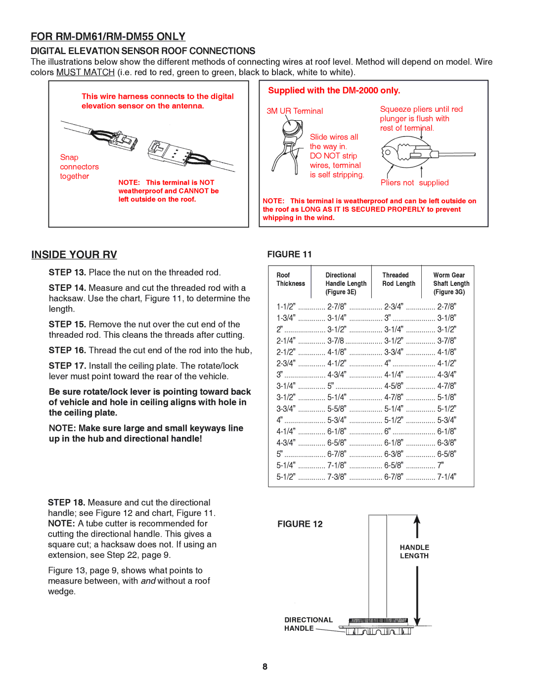
The illustrations below show the different methods of connecting wires at roof level. Method will depend on model. Wire colors MUST MATCH (i.e. red to red, green to green, black to black, white to white).
This wire harness connects to the digital
Supplied with the DM-2000 only.
elevation sensor on the antenna.
Snap connectors together
NOTE: This terminal is NOT weatherproof and CANNOT be
3M UR Terminal
Slide wires all the way in. DO NOT strip wires, terminal is self stripping.
Squeeze pliers until red plunger is flush with rest of terminal.
Pliers not supplied
left outside on the roof.
NOTE: This terminal is weatherproof and can be left outside on the roof as LONG AS IT IS SECURED PROPERLY to prevent whipping in the wind.
INSIDE YOUR RV
STEP 13. Place the nut on the threaded rod.
STEP 14. Measure and cut the threaded rod with a hacksaw. Use the chart, Figure 11, to determine the length.
STEP 15. Remove the nut over the cut end of the threaded rod. This cleans the threads after cutting.
STEP 16. Thread the cut end of the rod into the hub,
STEP 17. Install the ceiling plate. The rotate/lock lever must point toward the rear of the vehicle.
Be sure rotate/lock lever is pointing toward back of vehicle and hole in ceiling aligns with hole in the ceiling plate.
NOTE: Make sure large and small keyways line up in the hub and directional handle!
STEP 18. Measure and cut the directional handle; see Figure 12 and chart, Figure 11. NOTE: A tube cutter is recommended for cutting the directional handle. This gives a square cut; a hacksaw does not. If using an extension, see Step 22, page 9.
Figure 13, page 9, shows what points to measure between, with and without a roof wedge.
FIGURE 11
Roof | Directional | Threaded | Worm Gear |
Thickness | Handle Length | Rod Length | Shaft Length |
| (Figure 3E) |
| (Figure 3G) |
3” | |||
2” | |||
4” | |||
3” | |||
5” | |||
4” | |||
6” | |||
5” | |||
7” | |||
|
|
|
|
|
|
|
|
|
FIGURE 12 |
|
| ³ | |
|
|
|
| |
|
|
| HANDLE | |
|
|
| LENGTH | |
|
|
|
|
|
|
|
| DIRECTIONAL |
|
|
|
|
|
| ³ | ||
| HANDLE |
| |||
|
|
|
| ||
|
|
|
|
|
|
8