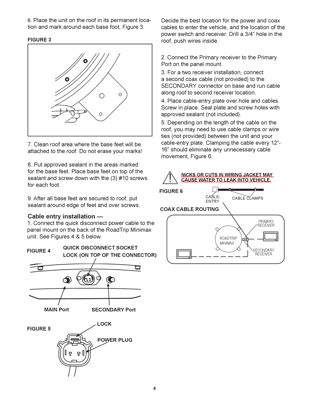
6.Place the unit on the roof in its permanent loca- tion and mark around each base foot, Figure 3.
FIGURE 3
7.Clean roof area where the base feet will be attached to the roof. Do not erase your marks!
8.Put approved sealant in the areas marked for the base feet. Place base feet on top of the sealant and screw down with the (3) #10 screws for each foot.
9.After all base feet are secured to roof, put sealant around edge of feet and over screws.
Cable entry installation —
1.Connect the quick disconnect power cable to the panel mount on the back of the RoadTrip Minimax unit. See Figures 4 & 5 below.
FIGURE 4 | QUICK DISCONNECT SOCKET | |
LOCK (ON TOP OF THE CONNECTOR) | ||
|
MAIN Port | SECONDARY Port |
Decide the best location for the power and coax cables to enter the vehicle, and the location of the power switch and receiver. Drill a 3/4” hole in the roof, push wires inside.
2.Connect the Primary receiver to the Primary Port on the panel mount.
3.For a two receiver installation, connect
a second coax cable (not provided) to the SECONDARY connector on base and run cable along roof to second receiver location.
4.Place
5.Depending on the length of the cable on the roof, you may need to use cable clamps or wire ties (not provided) between the unit and your
!NICKS OR CUTS IN WIRING JACKET MAY CAUSE WATER TO LEAK INTO VEHICLE.
FIGURE 6
Cable- | Cable CLAMPS | |
entry | ||
|
COAX CABLE ROUTING
PRIMARY
RECEIVER
RoadTrip
Minimax
SECONDARY
RECEIVER
FIGURE 5
LOCK
POWER PLUG
4