Appendix:
Making the Right Connection with Hex Connectors
Making a coaxial cable connection is critical. If you have the basic technique right you can modify it to your own personal taste. Whether you use a knife, stripping tool or diagonal cutter, the important thing is to make a good clean cut. A hex crimping tool is required for hex connectors, for maximum RF transmis- sion.
As mentioned before, the choice of tools is yours. Be sure you do a precise job. Failure to do so can cost you time and money in trying to locate a system problem.
Cut the cable flush. Strip the outer jacket off 1/2”, then trim the dielectric by cutting partially thru. DO NOT NICK THE CENTER CONDUCTOR! Twist and pull off leaving a 1/2” minu- mum of exposed center conductor.
Remove additional 1/4” of the outer jacket.Pull the braid away from the dielectric and fold over the jacket.
If there’s any residue on the center conductor scrape off with
Slide connector onto coax. Trim off excess braid.
Look into end of connector to make sure no braid or aluminum foil touches or has the possibility of touching the center conductor. Shorting can result if either comes in contact with center conductor. Close crimping tool making correct crimp.
IN HOT WEATHER: Trim off center conductor leaving 3/16” beyond the connector. The center conductor expands at higher temperatures. If a little extra is not provided, it may contract enough in the winter to cre- ate an open connection and result in loss of picture.
IN COLD WEATHER OR INDOORS: Trim off center conductor leaving it extended 1/16” of an inch beyond the connector. (Use diagonal pliers for cutting center conductor).
EMERGENCY MANUAL STOW
1.Unplug TRAV’LER Interface.
2.Remove the black plastic bolt from the back of the mount.
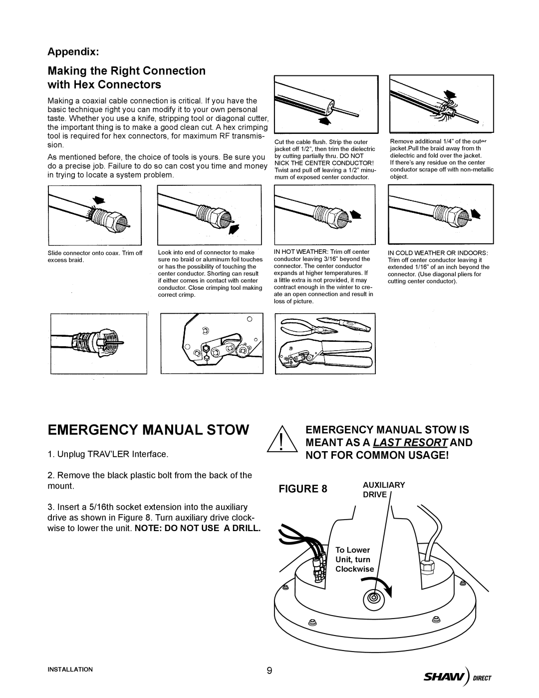
3.Insert a 5/16th socket extension into the auxiliary drive as shown in Figure 8. Turn auxiliary drive clock- wise to lower the unit. NOTE: DO NOT USE A DRILL.
EMERGENCY MANUAL STOW IS ! MEANT AS A LAST RESORT AND
NOT FOR COMMON USAGE!
FIGURE 8 | AUXILIARY | |
DRIVE | ||
|
To Lower
Unit, turn
Clockwise
INSTALLATION | 9 |