ASSEMBLY
Assembly of this mower is the responsibility of the Woods dealer. It should be delivered to the owner com- pletely assembled, lubricated, and adjusted for normal cutting conditions.
Refer to mower frame assembly illustrations and parts list. Lay out parts and hardware on a clean surface to aid in assembly.
AARNING
■Keep all persons away from the operator con- trol area while performing adjustments, service or maintenance.
A
■Always wear relatively tight and belted clothing to avoid entanglement in moving parts. Wear sturdy,
Side Shields (See page 16)
Attach side shields to the mower with 3/8 x 1" cap screws and flange lock nuts. A side discharge chute
(60)may be installed on the right end of the mower in place of side shield (54).
Center Belt Shield (See page 16)
Bolt center belt shield bracket (21) to mower deck in hole just behind center spindle using 3/8 x 1" bolt, lock washer and nut. Bolt center shield (22) to this bracket and to deck, using the three bolts welded in them. Secure with 3/8" nuts and lock washers.
Side Skids (See page 16)
Bolt the side skids on in such a position that they will be carried close to the ground when the mower is oper- ated at the desired mowing height. Use 3/8 x
Fast Hitch
To use
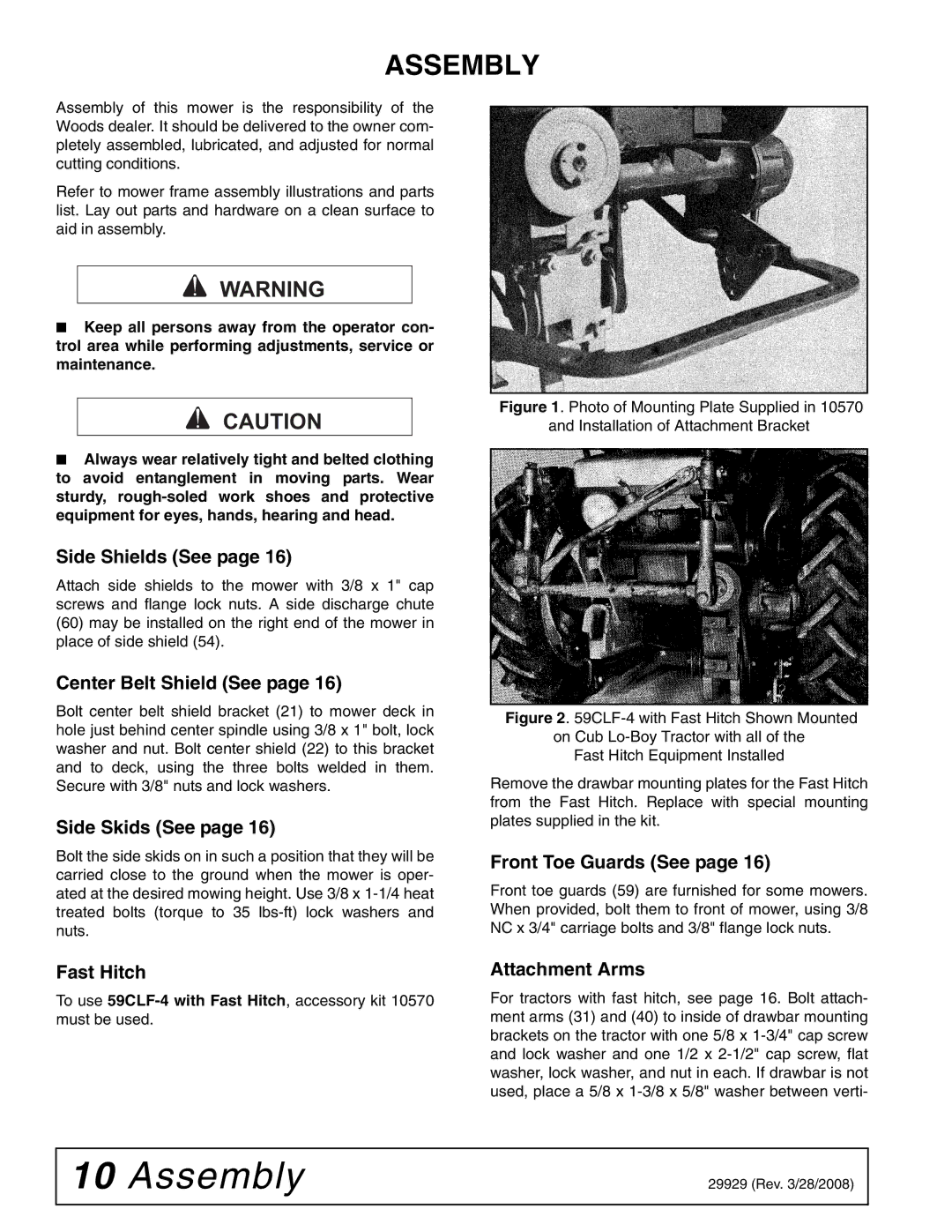
Figure 1. Photo of Mounting Plate Supplied in 10570
and Installation of Attachment Bracket
Figure 2. 59CLF-4 with Fast Hitch Shown Mounted on Cub Lo-Boy Tractor with all of the
Fast Hitch Equipment Installed
Remove the drawbar mounting plates for the Fast Hitch from the Fast Hitch. Replace with special mounting plates supplied in the kit.
Front Toe Guards (See page 16)
Front toe guards (59) are furnished for some mowers. When provided, bolt them to front of mower, using 3/8 NC x 3/4" carriage bolts and 3/8" flange lock nuts.
Attachment Arms
For tractors with fast hitch, see page 16. Bolt attach- ment arms (31) and (40) to inside of drawbar mounting brackets on the tractor with one 5/8 x
10 Assembly | 29929 (Rev. 3/28/2008) |
|
|
