INSTALL OPTIONAL STABILIZER STREET PAD
1.Remove cotter pins, headless pin, and stabilizer pad from the end of each stabilizer arm.
NOTE: On earlier stabilizer arms the mounting holes are not available, holes will have to be drilled. See Figure 21 to locate and drill two 25/64” (.391”) holes on the back side (tractor side) of the stabilizer arms.
Figure 21. Mounting Hole Location
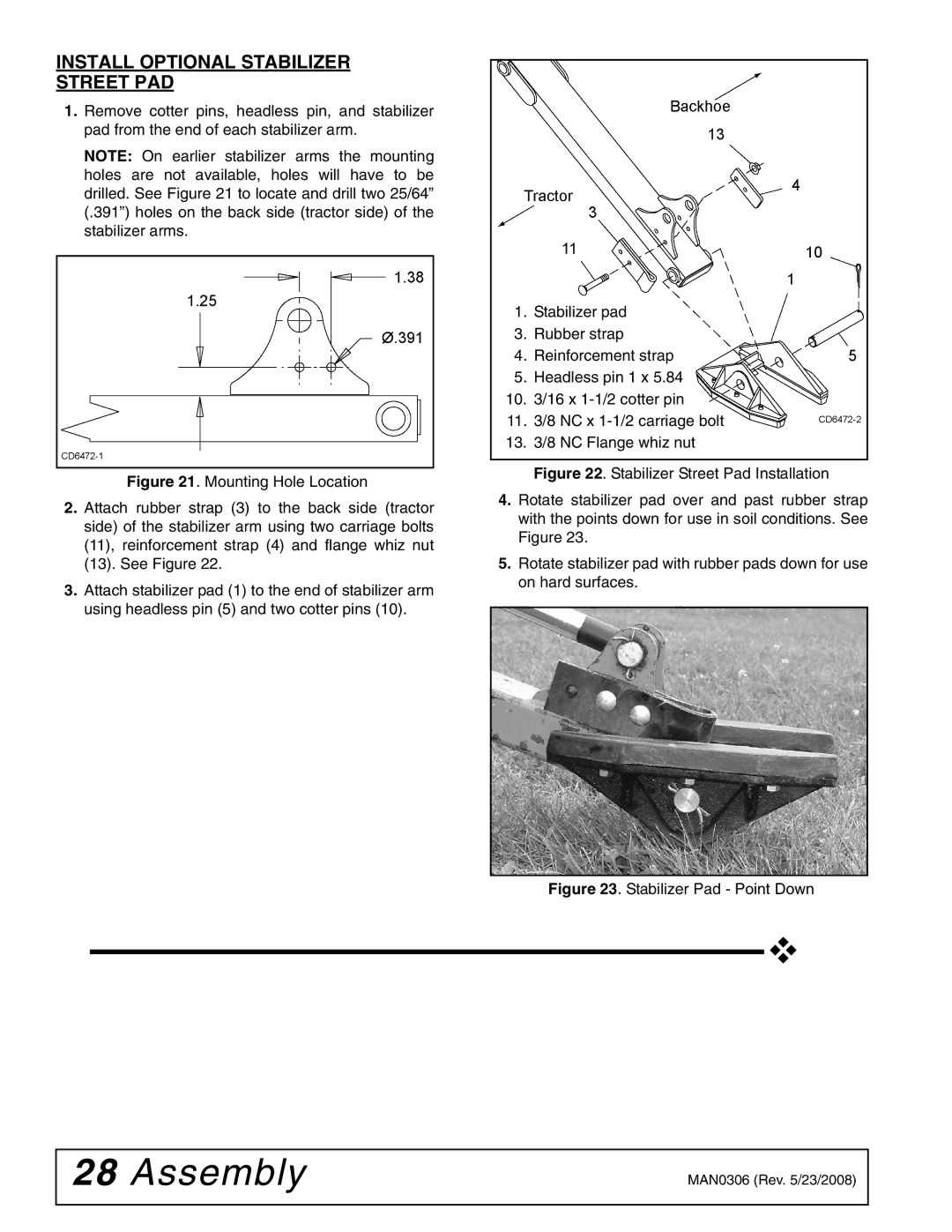
2.Attach rubber strap (3) to the back side (tractor side) of the stabilizer arm using two carriage bolts (11), reinforcement strap (4) and flange whiz nut (13). See Figure 22.
3.Attach stabilizer pad (1) to the end of stabilizer arm using headless pin (5) and two cotter pins (10).
1.Stabilizer pad
3.Rubber strap
4.Reinforcement strap
5.Headless pin 1 x 5.84
10.3/16 x 1-1/2 cotter pin
11.3/8 NC x 1-1/2 carriage bolt
13.3/8 NC Flange whiz nut
Figure 22. Stabilizer Street Pad Installation
4.Rotate stabilizer pad over and past rubber strap with the points down for use in soil conditions. See Figure 23.
5.Rotate stabilizer pad with rubber pads down for use on hard surfaces.
Figure 23. Stabilizer Pad - Point Down
28 Assembly | MAN0306 (Rev. 5/23/2008) |
|
|