ADJUST CONTROL VALVE LINKAGE
Reconnect control linkage to valve.
Control handles should be positioned as shown.
When completing a maintenance function on the valve, perform a functional test by placing control handles in their various positions and make certain the correct operation occurs corresponding to the decals on the operator's console. Pay specific attention to the float position of the boom. Do not operate backhoe if func- tions differ from the decal.
If the functions differ from the decal, check to make sure control linkage is correctly installed and check plumbing schematics to make sure hoses are correctly connected.
Figure 18. Control Lever Adjustment
HYDRAULIC CYLINDER REPAIR
General Hydraulic Repair Information
A clean working area is essential for any hydraulic repair.
All parts must be carefully cleaned before reassembly. We recommend that when repairing hydraulic compo- nents, you always replace existing seals with new ones. Clean all components in solvent and blow dry with low pressure air.
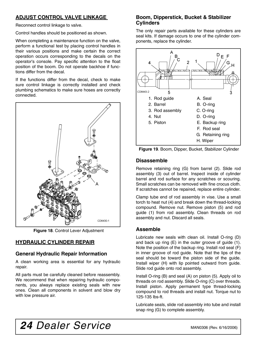
Boom, Dipperstick, Bucket & Stabilizer Cylinders
The only repair parts available for these cylinders are seal kits. If damage occurs to one of the cylinder com- ponents, replace the cylinder.
1. | Rod guide | A. Seal |
2. | Barrel | B. |
3. | Rod assembly | C. |
4. | Nut | D. |
5. | Piston | E. Backup ring |
|
| F. Rod seal |
G. Retaining ring
H. Wiper
Figure 19. Boom, Dipper, Bucket, Stabilizer Cylinder
Disassemble
Remove retaining ring (G) from barrel (2). Slide rod assembly (3) out of barrel. Inspect inside of cylinder barrel and rod surface for any scratches or scouring. Small scratches can be removed with fine crocus cloth. If scratches cannot be repaired, replace entire cylinder.
Clamp tube end of rod assembly in vise. Use a small torch to heat nut (4) and break down the
Assemble
Lubricate new seals with clean oil. Install
Install
Lubricate seals, slide rod assembly into tube and install snap ring (G) to complete assembly.
24 Dealer Service | MAN0306 (Rev. 6/16/2006) |
|
|