SUB-FRAME INSTALLATION Cont’d
Sub-Frame Fit-Up
1.Center
2.Insert cross tube of
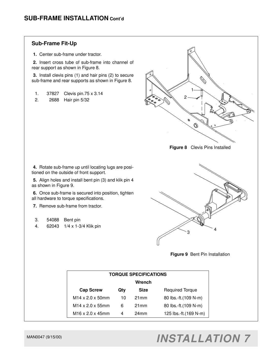
3.Install clevis pins (1) and hair pins (2) to secure
1.37827 Clevis pin.75 x 3.14
2.2688 Hair pin 5/32
1![]()
2
Figure 8 Clevis Pins Installed
4.Rotate sub-frame up until locating lugs are posi- tioned on the outside of front support.
5.Align holes and install bent pin (3) and klik pin 4
as shown in Figure 9.
6. Once sub-frame is secured into position, tighten all hardware to torque specifications.
7. Remove sub-frame from tractor.
3. | 54088 Bent pin |
|
|
|
|
|
|
| |
|
|
|
|
|
|
| |||
|
|
|
|
|
|
| |||
|
|
|
|
|
|
| |||
4. | 62043 1/4 x |
|
| 4 | |||||
|
|
|
|
| |||||
|
|
|
|
| 3 |
|
|
| |
|
|
|
|
|
| Figure 9 Bent Pin Installation | |||
|
|
|
|
|
| ||||
|
|
|
|
|
| ||||
|
|
|
|
|
| ||||
|
| TORQUE SPECIFICATIONS |
|
| |||||
|
|
|
| Wrench |
|
|
|
|
|
|
| Cap Screw | Qty | Size |
| Required Torque |
|
| |
|
| M14 x 2.0 x 50mm | 10 | 21mm |
| 80 |
|
| |
|
| M14 x 2.0 x 55mm | 6 | 21mm |
| 80 |
|
| |
|
| M16 x 2.0 x 45mm | 4 | 24mm |
| 125 |
|
| |
|
|
|
|
|
|
|
|
|
|
MAN0047 (9/15/00) | INSTALLATION 7 |
| |
|
|