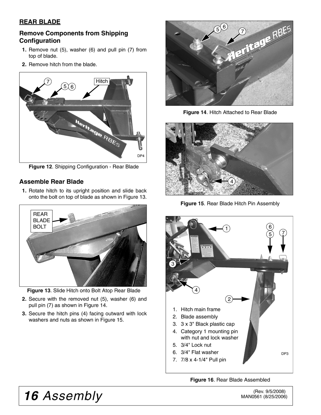
BSE4 specifications
The Woods Equipment BSE4 is a leading-edge attachment designed for those who need a reliable and efficient solution for their landscaping, agricultural, and maintenance needs. This high-performance equipment is specifically crafted to meet the rigorous demands of various tasks while ensuring maximum productivity.One of the standout features of the BSE4 is its robust build quality. Constructed with heavy-duty materials, it offers exceptional durability and resistance to wear and tear, making it suitable for use in tough environments. The solid frame ensures stability during operation, which is crucial for achieving precise results when tackling different tasks.
In terms of functionality, the BSE4 is designed to be versatile. It can be easily attached to a range of compatible tractors and utility vehicles, providing users with flexibility in their operations. This adaptability allows for seamless transitions between different jobs, whether it's clearing land, managing brush, or maintaining landscapes.
The BSE4 incorporates advanced technology to enhance its performance. It features a powerful hydraulic system that offers superior control and efficiency. This system enables the operator to easily adjust the speed and angle of the attachment, allowing for customized operation depending on the task at hand.
Another impressive characteristic of the BSE4 is its enhanced safety features. With a focus on user safety, it comes equipped with protective guards and shields that prevent debris from being propelled during use. This ensures a safer working environment for both the operator and bystanders.
The design of the BSE4 also prioritizes maintenance ease. With accessible components, routine maintenance tasks can be performed quickly and conveniently, minimizing downtime and increasing operational efficiency. The attachment’s intuitive design allows users to spend more time working and less time on upkeep.
Furthermore, the BSE4 is engineered for excellent performance in various terrain types. Whether working on soft soil, rocky landscapes, or uneven ground, its strong build and advanced design provide the stability and power needed to get the job done effectively.
In summary, the Woods Equipment BSE4 stands out as a formidable attachment that combines durability, versatility, and advanced technology. Its impressive features, including a powerful hydraulic system, robust construction, and user-friendly design, make it an essential tool for professionals seeking to maximize their productivity in demanding environments. With the BSE4, users can confidently tackle a wide range of tasks, ensuring exceptional results every time.

