2.Slide spacer (53) and
3.Attach base end of wing cylinder (4) to cylinder links (19 & 20) using clevis pin (54) and cotter pins (62).
4.Remove plug from base end of hydraulic cylinder. Align cylinder rod end with cylinder lug on the wing and insert
5.Slide spacer (21) over
6.Insert safety pin (61) into the end of
7.Extend cylinder fully & replace plug in base end of cylinder. This trapped air will help push wing down.
8.Install bushing (90), elbow, (69) and hose (59) to the rod end of cylinder (4). See Install Hose Kit, page 39 for complete instructions.
9.Repeat procedure for opposite wing.
NOTE: (BW126XR has only the right wing installed. BW126XL has only the left wing installed.)
19
20
16
|
|
| 18 |
|
|
| 62 |
| 53 |
|
|
|
|
| DP3 |
16. | Wing | 20. | Cylinder Link |
18. | 1 x 4.08 Clevis Pin | 53. | Spacer, 1" |
19. | Cylinder Link | 62. | 1/4 x |
|
|
| Pin |
Figure 32. Left Wing Lock-Up Bar Installed
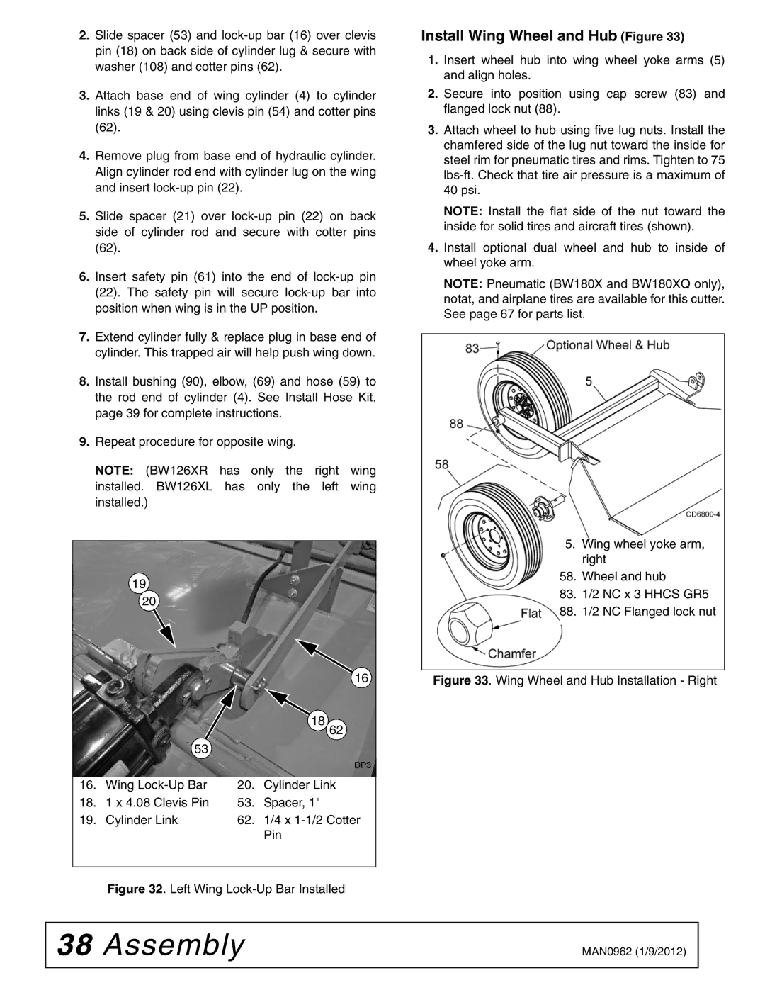
Install Wing Wheel and Hub (Figure 33)
1.Insert wheel hub into wing wheel yoke arms (5) and align holes.
2.Secure into position using cap screw (83) and flanged lock nut (88).
3.Attach wheel to hub using five lug nuts. Install the chamfered side of the lug nut toward the inside for steel rim for pneumatic tires and rims. Tighten to 75
NOTE: Install the flat side of the nut toward the inside for solid tires and aircraft tires (shown).
4.Install optional dual wheel and hub to inside of wheel yoke arm.
NOTE: Pneumatic (BW180X and BW180XQ only), notat, and airplane tires are available for this cutter. See page 67 for parts list.
5.Wing wheel yoke arm, right
58. Wheel and hub
83.1/2 NC x 3 HHCS GR5
88.1/2 NC Flanged lock nut
Figure 33. Wing Wheel and Hub Installation - Right
38 Assembly | MAN0962 (1/9/2012) |
|
|