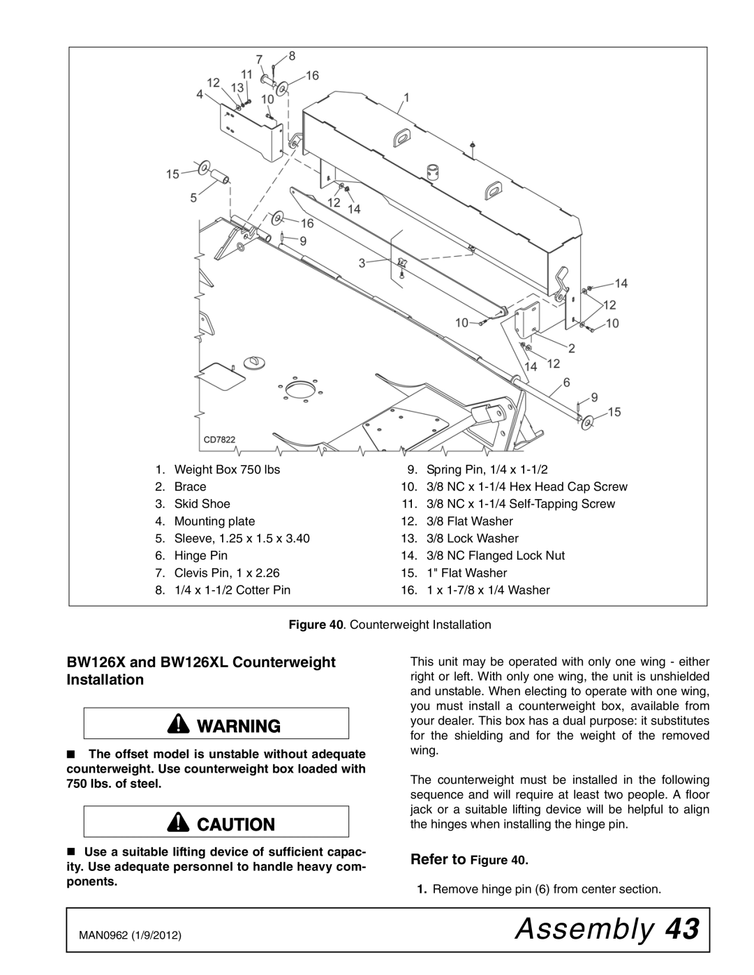
1. | Weight Box 750 lbs | 9. | Spring Pin, 1/4 x |
2. | Brace | 10. | 3/8 NC x |
3. | Skid Shoe | 11. | 3/8 NC x |
4. | Mounting plate | 12. | 3/8 Flat Washer |
5. | Sleeve, 1.25 x 1.5 x 3.40 | 13. | 3/8 Lock Washer |
6. | Hinge Pin | 14. | 3/8 NC Flanged Lock Nut |
7. | Clevis Pin, 1 x 2.26 | 15. | 1" Flat Washer |
8. | 1/4 x | 16. | 1 x |
|
|
|
|
Figure 40. Counterweight Installation
BW126X and BW126XL Counterweight Installation
■The offset model is unstable without adequate counterweight. Use counterweight box loaded with 750 lbs. of steel.
![]() CAUTION
CAUTION
Use a suitable lifting device of sufficient capac- ity. Use adequate personnel to handle heavy com- ponents.
This unit may be operated with only one wing - either right or left. With only one wing, the unit is unshielded and unstable. When electing to operate with one wing, you must install a counterweight box, available from your dealer. This box has a dual purpose: it substitutes for the shielding and for the weight of the removed wing.
The counterweight must be installed in the following sequence and will require at least two people. A floor jack or a suitable lifting device will be helpful to align the hinges when installing the hinge pin.
Refer to Figure 40.
1.Remove hinge pin (6) from center section.
MAN0962 (1/9/2012) | Assembly 43 |
|
|