L306 K50 specifications
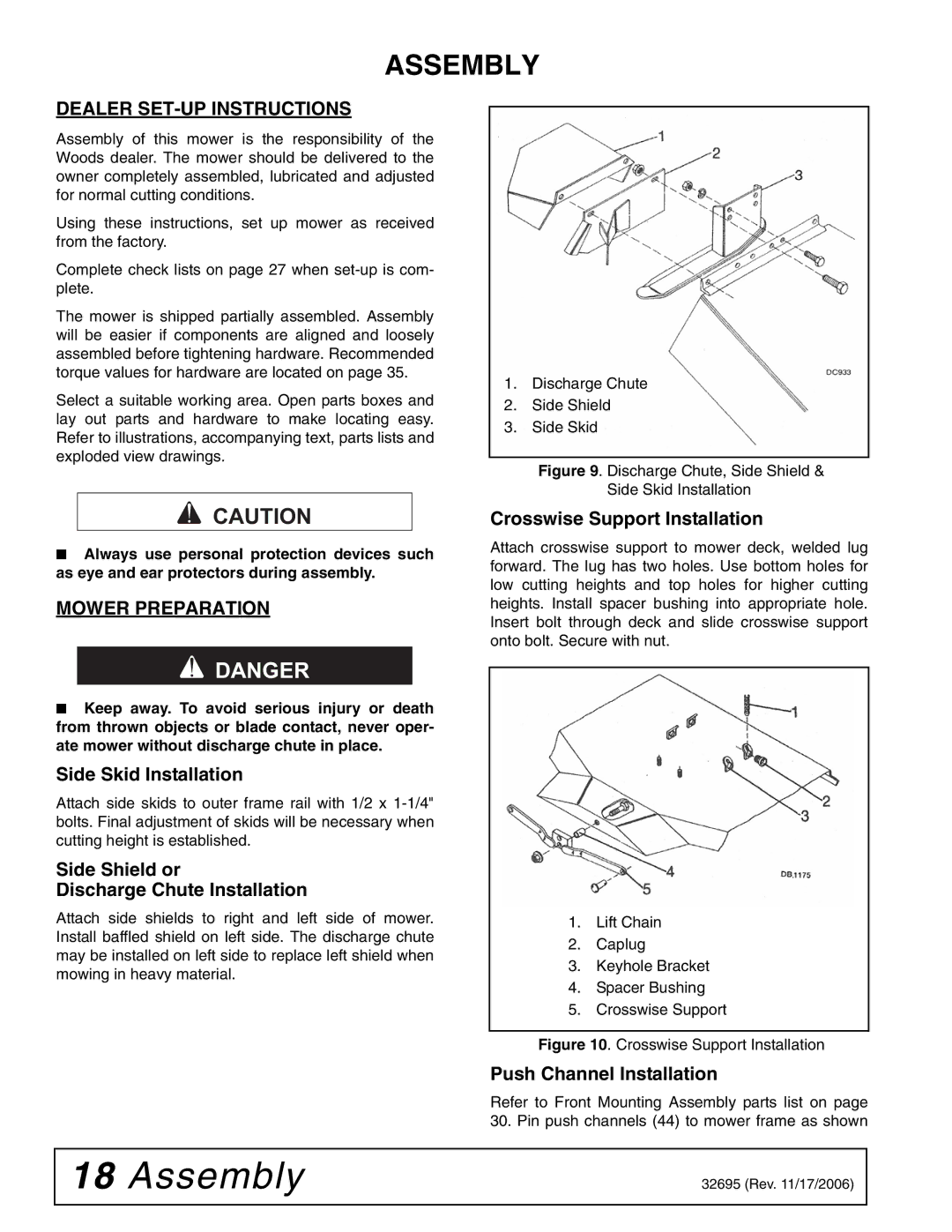
Woods Equipment L306 K50 is a robust and reliable tool designed specifically for agricultural and landscaping applications. This versatile equipment offers various features that enhance its performance, making it a valuable asset for farmers, landscapers, and contractors alike.One of the standout features of the L306 K50 is its impressive cutting width. With a cutting width of 6 feet, this mower allows for efficient and quick mowing, significantly reducing the time it takes to maintain large areas. The high-quality blades ensure a clean and precise cut, contributing to a well-manicured appearance for lawns and fields.
The construction of the L306 K50 is another highlight. Made with heavy-duty, durable materials, it is engineered to withstand tough conditions and heavy use. The robust frame provides stability and strength, allowing it to tackle more challenging terrains without compromising performance. This durability means less downtime for repairs and more time spent on the job.
Advanced technologies integrated into the L306 K50 further increase its efficiency. The mower features a unique deck design that optimizes airflow, resulting in superior grass lift. This design helps to ensure an even cut and contributes to a healthier lawn by promoting proper grass growth. Additionally, the mower's adjustable cutting height allows users to customize their cutting experience according to the specific requirements of different grass types and terrain.
Operator comfort and control are prioritized in the L306 K50. The user-friendly controls are designed for ease of operation, allowing both seasoned professionals and novice users to handle the machinery effectively. Furthermore, the mower’s compact design enhances maneuverability, making it suitable for navigating tight spaces and obstacles commonly found in landscaped areas.
Maintenance is simplified with the Woods Equipment L306 K50. The mower is designed for easy access to key components, making routine inspections and maintenance tasks straightforward. This thoughtful design ensures that users can keep their equipment in optimal condition without the need for extensive tools or time.
Overall, the Woods Equipment L306 K50 stands out for its blend of power, versatility, and user-friendly design. With its high cutting performance, durable construction, and advanced features, it is an excellent choice for anyone looking to maintain expansive landscapes or agricultural areas with efficiency and ease. Whether for professional landscaping or personal use, the L306 K50 is designed to deliver outstanding results in a wide array of mowing tasks.

