L59, L36 specifications
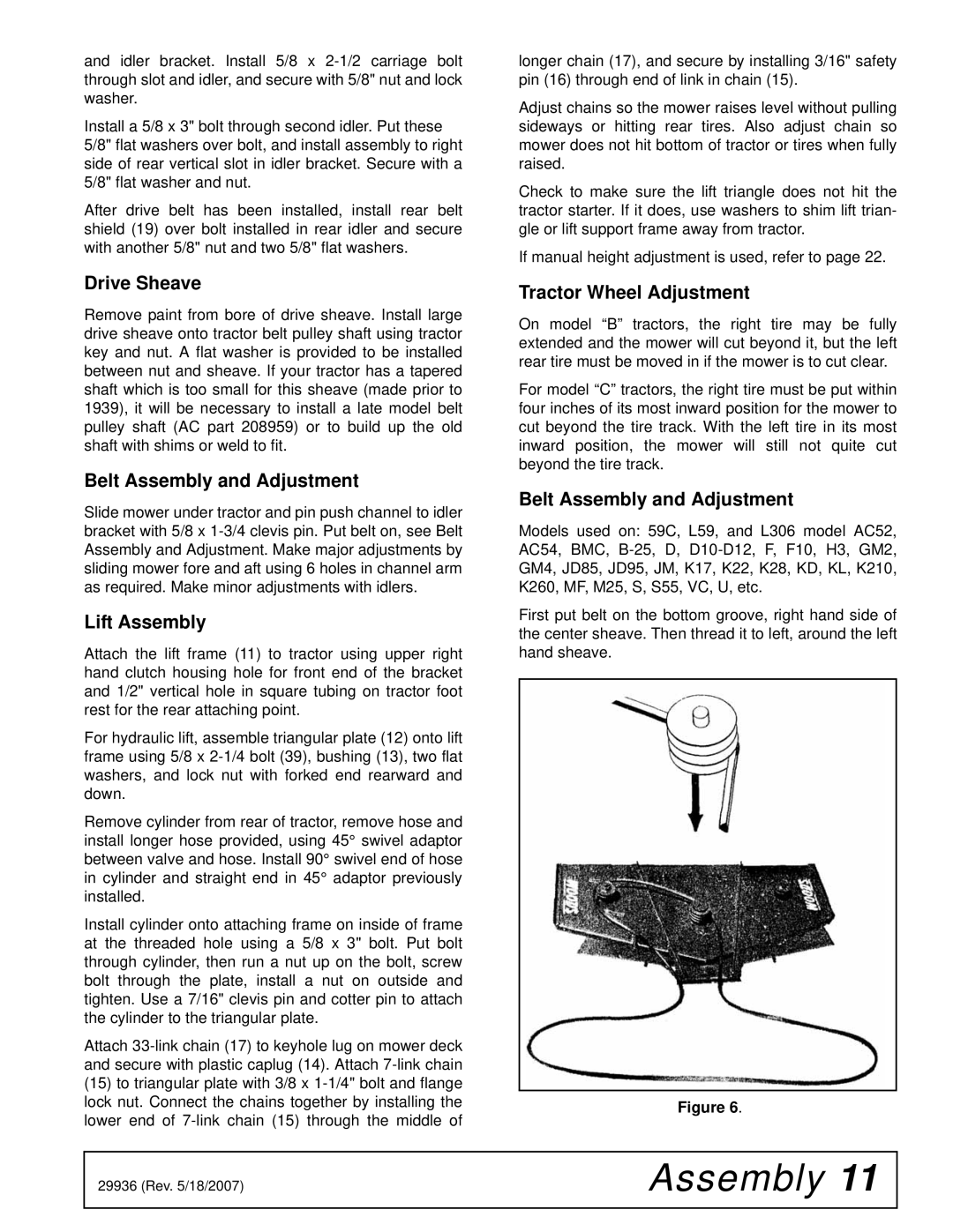
Woods Equipment has established itself as a leader in the agricultural equipment sector, particularly with its versatile line of mowers and rotary cutters. Among its notable models are the Woods L59 and L36, designed to meet the diverse needs of landowners, landscapers, and agricultural professionals.The Woods L59 is a robust rotary cutter renowned for its efficiency and durability. It features a cutting width of 59 inches, making it ideal for tackling larger areas while providing a clean and even cut. One of the standout characteristics of the L59 is its heavy-duty construction. Built with a reinforced frame and tough, high-quality steel deck, this rotary cutter can withstand the rigors of demanding mowing conditions. The L59 also incorporates a unique blade system that optimizes cutting performance, reducing the risk of stalling even in thick brush or overgrown grass.
In contrast, the Woods L36 is a more compact model that still delivers exceptional performance. With a cutting width of 36 inches, it is perfect for smaller properties and tight spaces where larger equipment may struggle. The L36 is engineered with similar durability in mind; however, its lighter design allows for easier maneuverability without sacrificing robustness. This model is particularly popular among hobby farmers and landscapers who require efficiency in tight corners and intricate landscaping tasks.
Both models are equipped with innovative technologies to enhance operational efficiency. The Woods L59 and L36 feature adjustable cutting heights, giving operators the flexibility to customize their mowing experience based on the specific needs of their terrain. Additionally, these rotary cutters are designed for compatibility with a variety of tractors, ensuring seamless integration into existing equipment fleets.
Maintenance is also straightforward with both the L59 and L36, thanks to easily accessible components. This user-friendly design reduces downtime, allowing operators to keep their equipment in peak condition and maximize productivity.
In summary, Woods Equipment's L59 and L36 models exemplify reliability, flexibility, and performance. Whether managing large expanses of land or tending to smaller gardens, these rotary cutters stand out in their category, reflecting the company's commitment to quality and innovation in agricultural machinery.

