490-85 specifications
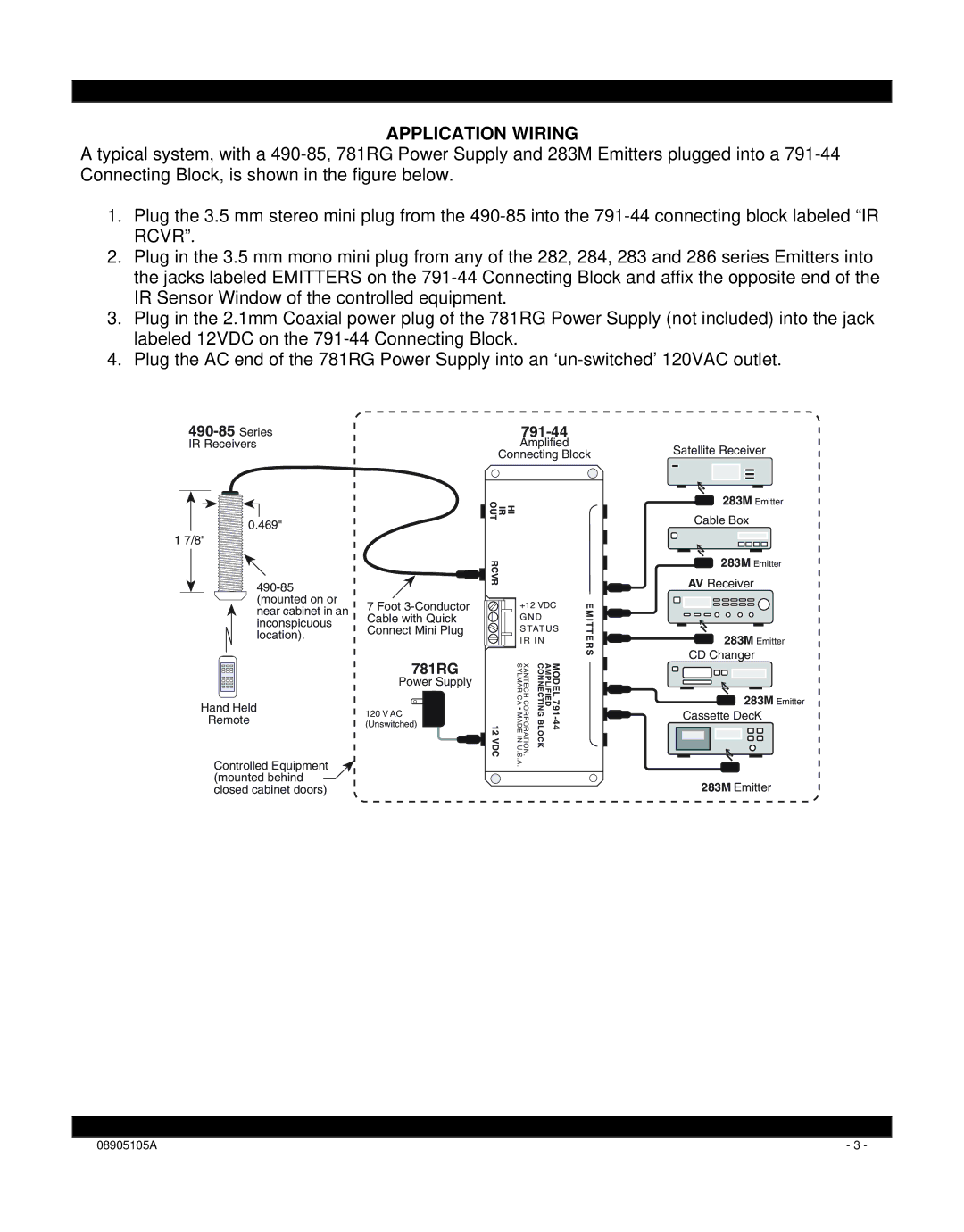
The Xantech 490-85 is a sophisticated infrared (IR) distribution amplifier designed specifically for enhancing audio and video installation systems. Its well-engineered features cater to both residential and commercial settings, making it an essential component for integrators requiring high-performance signal distribution.At the core of the Xantech 490-85 is its ability to expand IR control outputs. The device takes a single IR signal and distributes it to multiple devices, enabling seamless control of various components within a home theatre or multi-room setup. This versatility is ideal for users who need to control several AV devices from a centralized location without having to struggle with multiple remotes.
One of the standout features of the Xantech 490-85 is its ability to support up to eight output ports. This multiple output capability ensures that users can connect an extensive range of devices, from televisions and DVD players to cable boxes and streaming devices, all while maintaining consistent signal quality. The amplifier is built to minimize signal degradation, ensuring that the integrity of the IR commands remains intact, even over long distances.
The technology behind the Xantech 490-85 employs advanced signal boosting capabilities, which facilitate the transfer of IR signals over extended runs of cable. This means that users can expect robust and reliable operation, even in larger spaces where traditional systems might falter. The device also includes built-in short circuit protection, safeguarding the system from potential damage caused by improper connections.
Another characteristic that elevates the Xantech 490-85 is its ease of installation. The user-friendly design allows installers to set up the unit quickly and efficiently without extensive technical knowledge. The compact appearance ensures that the device can be discreetly integrated into existing systems without causing clutter.
In summary, the Xantech 490-85 stands out as a reliable and efficient IR distribution amplifier that enhances control capabilities within audio and video installations. Its multiple output options, advanced technologies, and straightforward installation make it a favored choice for professional integrators and enthusiasts alike. With this device, managing multiple AV components becomes a hassle-free experience, paving the way for a streamlined and enjoyable multimedia environment.

