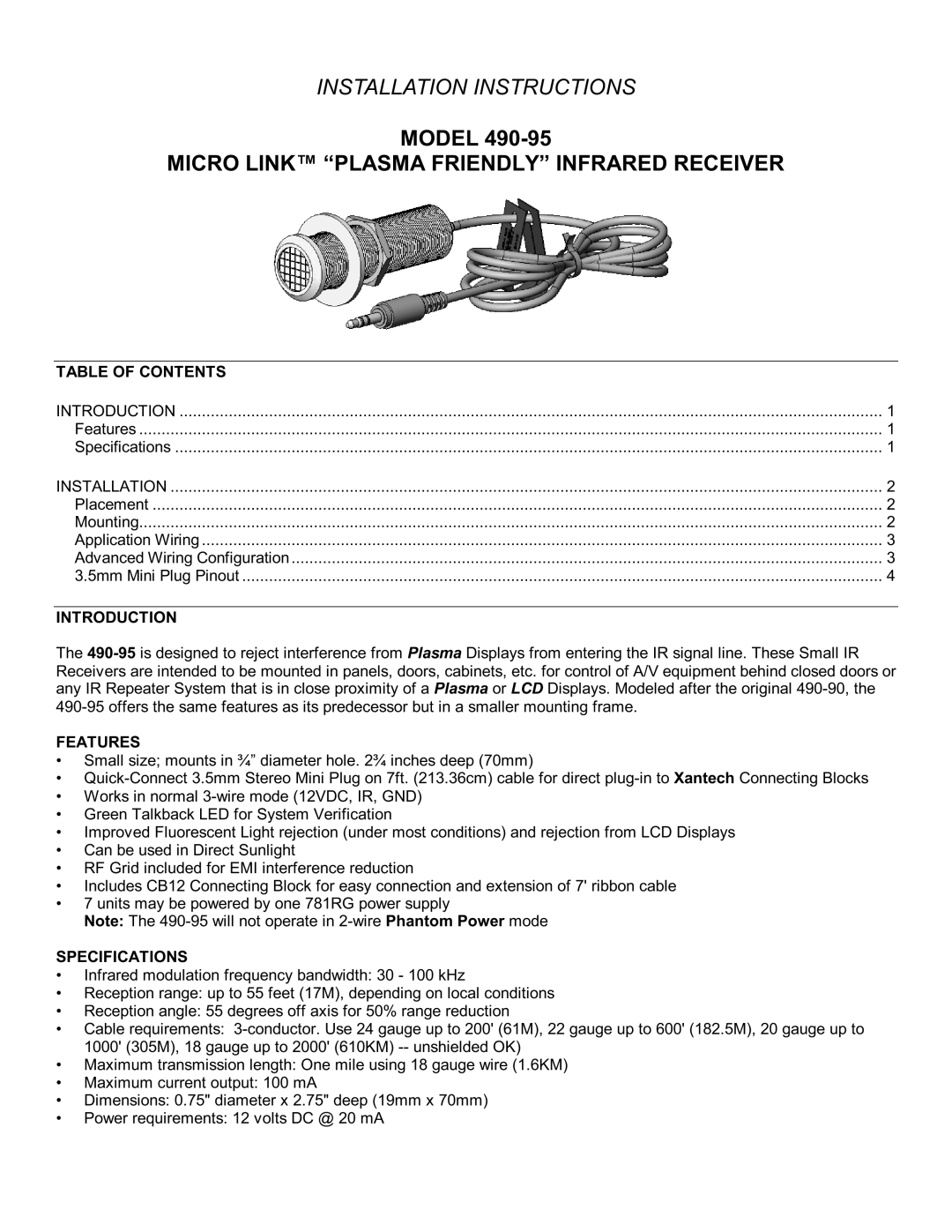
490-95 specifications
The Xantech 490-95 is a powerful and versatile product designed specifically for audio and video distribution systems. This device is well-suited for both residential and commercial applications, offering a range of features that cater to the needs of modern AV environments. One of the key offerings of the 490-95 is its ability to facilitate seamless integration of various audio and video sources, making it easier for users to manage and control their media.At the heart of the Xantech 490-95 is innovative technology that ensures high-quality signal transmission. This unit utilizes advanced signal processing technologies, which enhance the clarity and fidelity of audio and video signals. The integration of these technologies ensures that users experience minimal latency and superior performance across different media formats. Furthermore, the 490-95 is engineered to accommodate a variety of connections, including HDMI, composite, and component inputs and outputs, providing users with flexibility in their setups.
Another noteworthy feature of the 490-95 is its robust control capabilities. The device supports a range of control protocols, such as IR (infrared), RS-232, and LAN control. This flexibility enables users to easily integrate the 490-95 into existing home automation systems and allows for remote operation via smartphones and tablets. Users can customize their configurations to suit their specific needs, streamlining the management of multiple devices from a single interface.
The device also boasts a high level of reliability and durability. Designed with high-quality materials, the 490-95 can withstand the rigors of daily use in a busy AV environment. Additionally, it offers features such as surge protection and thermal management, which further enhance its performance and longevity.
In terms of user-friendliness, the Xantech 490-95 is equipped with an intuitive interface that simplifies setup and operation. Clear labeling and logical button placement make it easy for users of all levels of expertise to navigate through the various functions and features.
In summary, the Xantech 490-95 stands out in the realm of audio and video distribution systems due to its advanced technologies, flexibility in connectivity options, robust control capabilities, and ease of use. Whether in a home theater or a commercial setting, this device is designed to meet the demands of diverse AV applications while providing a seamless user experience. Its combination of performance, reliability, and versatility makes the 490-95 an excellent choice for anyone looking to elevate their audio and video experience.

