•Note that, as in Fig. 3, the N/O (normally open) contacts are connected to the screen and projector lift's MOMENTARY terminals. This allows the momentary action to occur.
•As a practical matter, it will be necessary to see that the projector and the screen positions are both UP prior to the issuance of the first command. This will ensure that their actions will be synchronized so that they will both travel in the correct direction when activated.
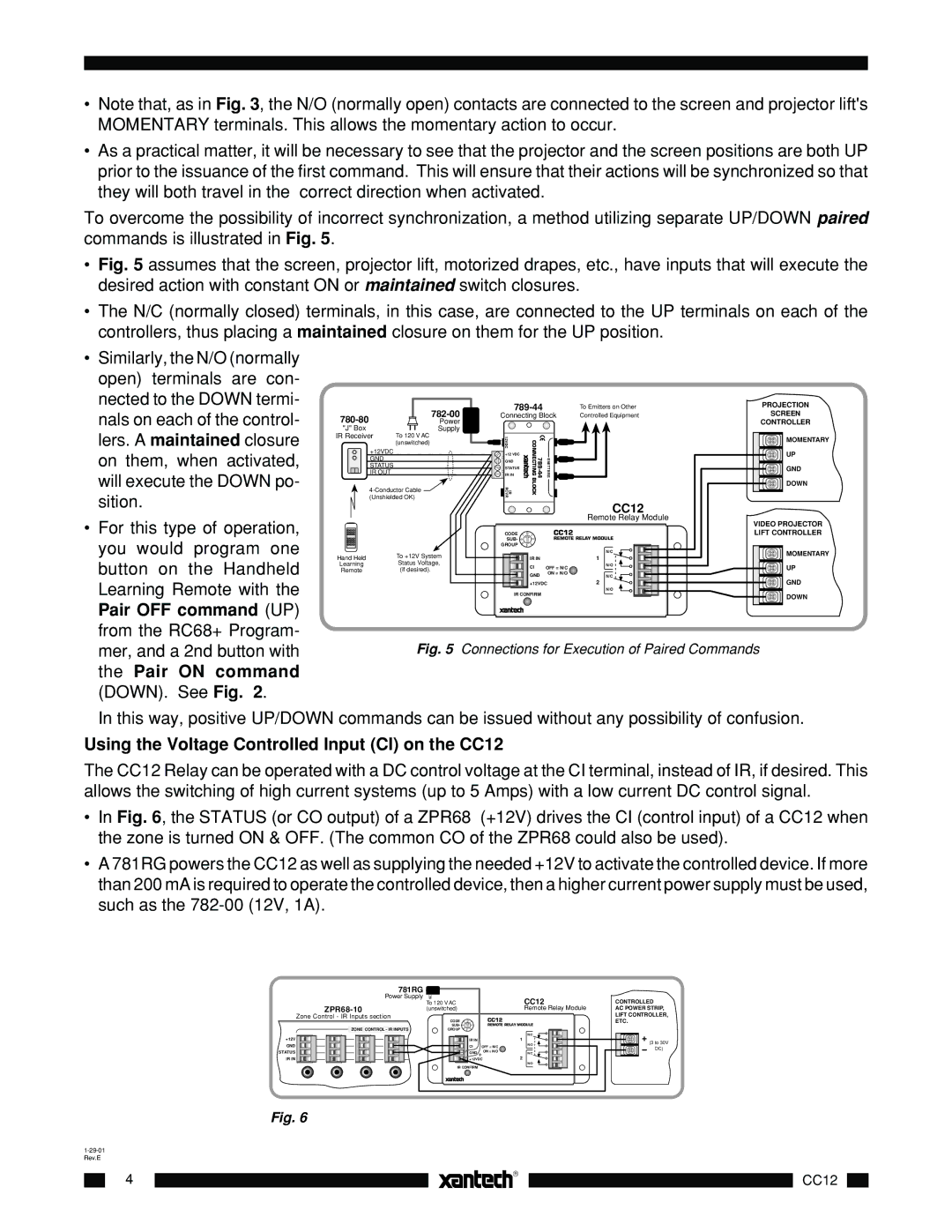
To overcome the possibility of incorrect synchronization, a method utilizing separate UP/DOWN paired commands is illustrated in Fig. 5.
•Fig. 5 assumes that the screen, projector lift, motorized drapes, etc., have inputs that will execute the desired action with constant ON or maintained switch closures.
•The N/C (normally closed) terminals, in this case, are connected to the UP terminals on each of the controllers, thus placing a maintained closure on them for the UP position.
• Similarly, the N/O (normally |
open) terminals are con- |
nected to the DOWN termi- |
nals on each of the control- |
lers. A maintained closure |
on them, when activated, |
will execute the DOWN po- |
sition. |
• For this type of operation, |
you would program one |
button on the Handheld |
Learning Remote with the |
Pair OFF command (UP) |
from the RC68+ Program- |
|
|
| |
| Power |
| |
"J" Box |
| Supply |
|
IR Receiver | To 120 V AC |
| |
| (unswitched) |
| |
+12VDC
GND STATUS IR OUT
![]()
(Unshielded OK)
Hand Held | To +12V System |
Learning | Status Voltage, |
Remote | (if desired). |
| To Emitters on Other |
Connecting Block | Controlled Equipment |
12VDC | CONNECTINGBLOCK | EMITTERS | |
IR RCVR | |||
+12 VDC |
|
|
|
GND |
|
|
|
STATUS |
|
|
|
IR IN |
|
|
|
CC12
Remote Relay Module
CODE | 7 | 0 | 1 |
| CC12 |
|
SUB- | 6 |
| 2 |
| REMOTE RELAY MODULE | |
GROUP | 5 | 4 | 3 |
|
|
|
|
|
|
|
| ||
|
|
|
|
|
| N/C |
|
|
| IR IN |
|
| 1 |
|
|
| CI | OFF = N/C | N/O | |
|
|
|
| |||
|
|
| GND |
| ON = N/O | N/C |
|
|
|
|
| ||
|
|
| +12VDC |
| 2 | |
|
|
|
|
|
| N/O |
IR CONFIRM
PROJECTION |
SCREEN |
CONTROLLER |
MOMENTARY |
UP |
GND |
DOWN |
VIDEO PROJECTOR |
LIFT CONTROLLER |
MOMENTARY |
UP |
GND |
DOWN |
mer, and a 2nd button with |
the Pair ON command |
(DOWN). See Fig. 2. |
Fig. 5 Connections for Execution of Paired Commands
In this way, positive UP/DOWN commands can be issued without any possibility of confusion.
Using the Voltage Controlled Input (CI) on the CC12
The CC12 Relay can be operated with a DC control voltage at the CI terminal, instead of IR, if desired. This allows the switching of high current systems (up to 5 Amps) with a low current DC control signal.
•In Fig. 6, the STATUS (or CO output) of a ZPR68 (+12V) drives the CI (control input) of a CC12 when the zone is turned ON & OFF. (The common CO of the ZPR68 could also be used).
•A 781RG powers the CC12 as well as supplying the needed +12V to activate the controlled device. If more than 200 mA is required to operate the controlled device, then a higher current power supply must be used, such as the
| 781RG |
|
|
|
| Power Supply | To 120 V AC | CC12 | |
|
| |||
|
| (unswitched) | Remote Relay Module | |
Zone Control - IR Inputs section | CODE | 7 | 0 | 1 |
| CC12 |
|
|
|
| |||||
ZONE CONTROL - IR INPUTS | SUB- | 6 |
| 2 |
| REMOTE RELAY MODULE | |
GROUP | 5 | 4 | 3 |
|
|
| |
|
|
|
|
| |||
|
|
|
|
|
|
| N/C |
+12V |
|
|
| IR IN |
|
| 1 |
GND |
|
|
| CI | OFF = N/C | N/O | |
|
|
|
| ||||
STATUS |
|
|
| GND + ON = N/O | N/C | ||
IR IN |
|
|
| +12VDC |
| 2 | |
|
|
|
|
|
|
| N/O |
| IR CONFIRM |
|
|
| |||
CONTROLLED
AC POWER STRIP, LIFT CONTROLLER, ETC.
+
(3 to 30V
DC)
Fig. 6
|
|
|
4 |
| |
| ||
|
| |
|
|
|
|
|
|
CC12