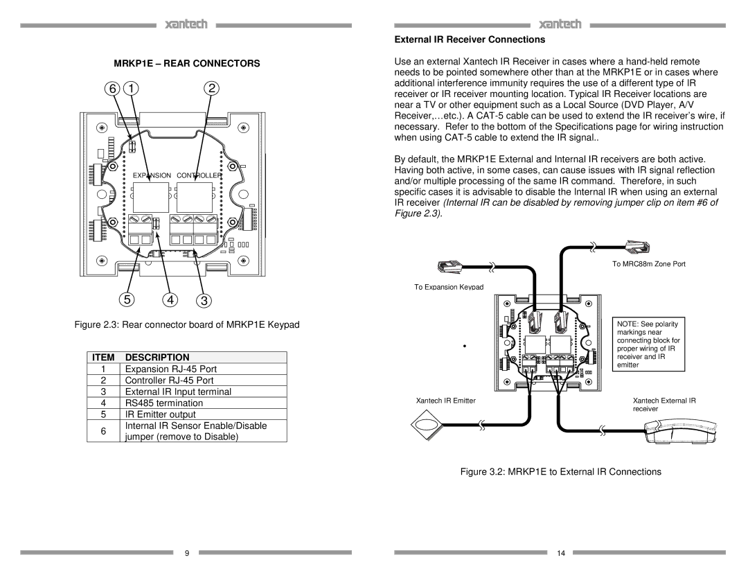
MRKP1E – REAR CONNECTORS
6 | 1 | 2 |
| EXPANSION | CONTROLLER |
5 4 3
Figure 2.3: Rear connector board of MRKP1E Keypad
ITEM DESCRIPTION
1Expansion
2Controller
3External IR Input terminal
4RS485 termination
5IR Emitter output
6 | Internal IR Sensor Enable/Disable | |
jumper (remove to Disable) | ||
|
9
External IR Receiver Connections
Use an external Xantech IR Receiver in cases where a
By default, the MRKP1E External and Internal IR receivers are both active. Having both active, in some cases, can cause issues with IR signal reflection and/or multiple processing of the same IR command. Therefore, in such specific cases it is advisable to disable the Internal IR when using an external IR receiver (Internal IR can be disabled by removing jumper clip on item #6 of Figure 2.3).
To MRC88m Zone Port
To Expansion Keypad
NOTE: See polarity markings near connecting block for proper wiring of IR receiver and IR emitter
Xantech IR Emitter | Xantech External IR |
| receiver |
Figure 3.2: MRKP1E to External IR Connections
14