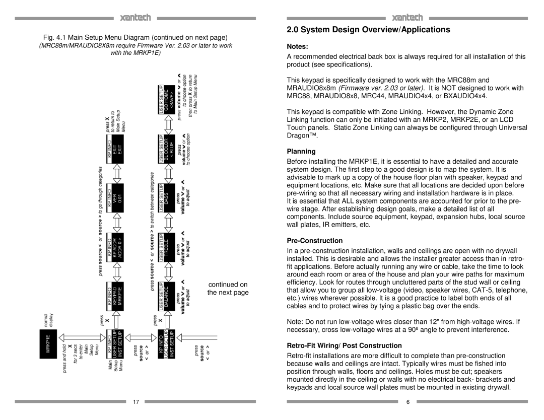
Fig. 4.1 Main Setup Menu Diagram (continued on next page)
(MRC88m/MRAUDIO8X8m require Firmware Ver. 2.03 or later to work
with the MRKP1E)
continued on the next page
17
2.0 System Design Overview/Applications
Notes:
A recommended electrical back box is always required for all installation of this product (see specifications).
This keypad is specifically designed to work with the MRC88m and MRAUDIO8x8m (Firmware ver. 2.03 or later). It is NOT designed to work with MRC88, MRAUDIO8x8, MRC44, MRAUDIO4x4, or BXAUDIO4x4.
This keypad is compatible with Zone Linking. However, the Dynamic Zone Linking function can only be initiated with an MRKP2, MRKP2E, or an LCD Touch panels. Static Zone Linking can always be configured through Universal Dragon™.
Planning
Before installing the MRKP1E, it is essential to have a detailed and accurate system design. The first step to a good design is to map the system. It is advisable to mark up a copy of the house floor plan with speaker, keypad and equipment locations, etc. Make sure that all locations are decided upon before
It is essential that ALL system components are accounted for prior to the pre- wire stage. After establishing design goals, make a detailed list of all components. Include source equipment, keypad, expansion hubs, local source wall plates, IR emitters, etc.
Pre-Construction
In a
Note: Do not run
Retro-Fit Wiring/ Post Construction
6