Installation

Mains Operating Voltage

Check that the instrument operating voltage marked on the rear panel is suitable for the local supply. Should it be necessary to change the operating voltage, proceed as follows:

1.Ensure that the instrument is disconnected from the AC supply.

2.Remove the screws holding the case upper and handle and lift off the case upper.

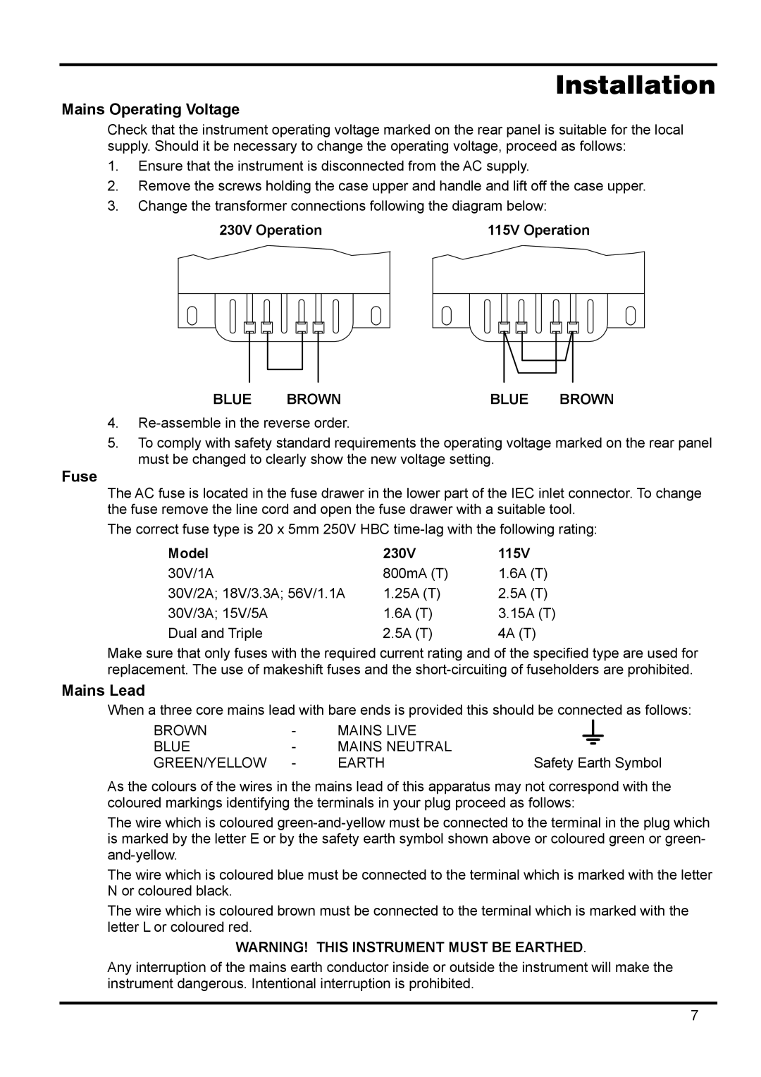
3.Change the transformer connections following the diagram below:


230V Operation

115V Operation


BLUE

BROWN

BLUE BROWN

4.Re-assemble in the reverse order.

5.To comply with safety standard requirements the operating voltage marked on the rear panel must be changed to clearly show the new voltage setting.

Fuse

The AC fuse is located in the fuse drawer in the lower part of the IEC inlet connector. To change the fuse remove the line cord and open the fuse drawer with a suitable tool.

The correct fuse type is 20 x 5mm 250V HBC time-lag with the following rating:

Model

230V

115V

30V/1A

800mA (T)

1.6A (T)

30V/2A; 18V/3.3A; 56V/1.1A

1.25A (T)

2.5A (T)

30V/3A; 15V/5A

1.6A (T)

3.15A (T)

Dual and Triple

2.5A (T)

4A (T)

Make sure that only fuses with the required current rating and of the specified type are used for replacement. The use of makeshift fuses and the short-circuiting of fuseholders are prohibited.

Mains Lead

When a three core mains lead with bare ends is provided this should be connected as follows:

BROWN

-

MAINS LIVE


BLUE

-

MAINS NEUTRAL


GREEN/YELLOW

-

EARTH

Safety Earth Symbol

As the colours of the wires in the mains lead of this apparatus may not correspond with the coloured markings identifying the terminals in your plug proceed as follows:

The wire which is coloured green-and-yellow must be connected to the terminal in the plug which is marked by the letter E or by the safety earth symbol shown above or coloured green or green- and-yellow.

The wire which is coloured blue must be connected to the terminal which is marked with the letter N or coloured black.

The wire which is coloured brown must be connected to the terminal which is marked with the letter L or coloured red.

WARNING! THIS INSTRUMENT MUST BE EARTHED.

Any interruption of the mains earth conductor inside or outside the instrument will make the instrument dangerous. Intentional interruption is prohibited.

7

Page 8
Image 8
Xantrex Technology XPL 56-1, XPL 30-2D, XPL 18-3 manual Installation, Mains Operating Voltage, Fuse, Mains Lead, Blue Brown

XPL 30-2T, XPL 30-1, XPL 30-2D, XPL 18-3, XPL 30-2 specifications

Xantrex Technology has established itself as a leader in the power solutions market, particularly with its innovative line of XPL inverter series. This series includes models XPL 56-1, XPL 30-2, XPL 18-3, XPL 30-2D, and XPL 30-1, each designed with unique features and characteristics to meet various power needs.

The XPL 56-1 is a powerhouse inverter known for its high output capacity, making it ideal for larger applications such as recreational vehicles or off-grid systems. With a robust design and advanced thermal management technology, this model can sustain heavy loads while ensuring reliability and efficiency. Its compact structure and lightweight design facilitate easy installation and flexibility in various setups.

The XPL 30-2 and XPL 30-2D models are tailored for users looking for a balance of power and portability. Both are equipped with advanced pure sine wave output, ensuring a clean and stable power supply that protects sensitive electronics. The XPL 30-2D variant features dual output options, allowing simultaneous powering of multiple devices, enhancing versatility for users in diverse environments.

For those with smaller power requirements, the XPL 18-3 is the perfect choice, offering a smaller footprint while still delivering robust performance. This model is optimized for efficiency, enabling longer battery life in applications like camping or marine use. Its user-friendly interface allows for easy monitoring and control, making it a favorite among casual users.

The XPL 30-1 stands out for its adaptability, supporting a range of input voltages and providing adjustable output settings. This model is particularly suited for industrial applications, thanks to its rugged construction and ability to withstand harsh environments. Advanced safety features, including overload protection and short-circuit prevention, ensure that both the inverter and connected devices remain safe during operation.

In summary, the Xantrex XPL inverter series provides cutting-edge technology and versatile solutions for various power demands. Each model is engineered with specific features to cater to different user needs, ensuring reliable power during outdoor adventures, industrial operations, or off-grid living. With Xantrex’s commitment to quality and innovation, the XPL series continues to set the standard in portable and stationary power systems.