LC 9 Quick Guide Sheet | P1 |
O V E R V I E W
P3
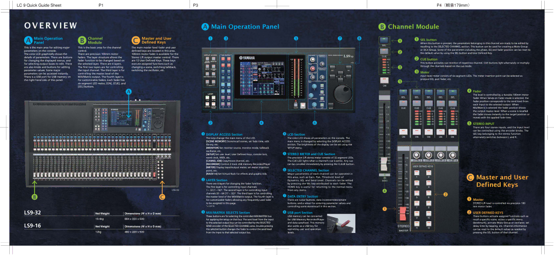
AMain Operation Panel
P4(観音179mm)
BChannel Module
A | Main Operation | B | Channel | C | Master and User |
Panel | Module | Defined Keys |
1 | 3 | 5 | 7 | 8 |
1 1
SEL button
When this button is pressed, the parameters belonging to this channel are ready to be edited by
This is the main area for editing major parameters on the console.
The color LCD graphically shows the details of parameters. There are buttons for changing the displayed menus, and for selecting output buses to edit. There are also knobs and buttons for editing parameter values. Some major parameters can be accessed instantly. There is a USB port for USB memory on the right hand side of this panel.
This is the basic area for the channel control.
There are precision 100mm motor faders. The layer structure allows the fader function to be changed based on the selected layer. There are 4 layers. The first two layers are for controlling the input channel. The third layer is for controlling the master level of the MIX/Matrix output. The fourth layer is for customizable faders. Each fader has
The main master level fader and user defined keys are located in this area. 100mm motor fader is available for the Stereo L/R output master control. There are 12 User Defined Keys. These keys execute assigned functions such as changing a scene, switching talkback, switching the oscillator, etc.
2
2
3
3
5
recalling to the SELECTED CHANNEL section. This button can be used for creating a Mute Group or DCA Group. Some of the parameters including the phase, EQ and fader position can be reset to the default value by using the SEL button and User Defined Key.
CUE button
This button activates cue monitor of respective channel. CUE buttons light alternately or multiply through the channels based on the cue mode.
Meter
Input level meter consists of
A
24
1DISPLAY ACCESS Section
The keys change the main menu of the LCD.
[SCENE MEMORY] Store/recall scenes, set fade time, edit library, etc.
[MONITOR] Set monitor source, monitor mode, talkback oscillator, etc.
[SETUP] Set user level, User Defined Keys, console lock, word clock, MIDI, etc.
[CANNEL JOB] Copy/move channel, etc.
[RECORDER] Control 2 track USB memory Recorder/Player [METER] Display input/output meter, set meter insertion point, etc.
2LAYER Section
There are 4 layers for changing the fader function. The first layer is for controlling input channels
6
4LCD Section
The color LCD shows all parameters on the console. The main menu is changed by selecting the DISPLAY ACCESS section. The brightness of the display can be set using the SETUP menu.
5STEREO METER and CUE Section
The precision L/R stereo meter consists of 32 segment LEDs. The CUE LED lights when a channel’s cue is active. Any cue can be canceled immediately by pressing the CLEAR button.
6SELECTED CHANNEL Section
Major parameters of each channel can be operated in this area, such as Gain, Pan, Threshold level of Dynamics, EQ, and Send Level. Channels can be edited by pressing the SEL key attributed to each fader. The HOME key is useful for returning to the normal menu
4Fader
The level is controlled by a durable 100mm motor fader. When Sends on Fader mode is selected, the fader position corresponds to the send level from each input to the selected output. When Mix/Matrix is selected the fader position shows the output master level. When a scene is recalled the fader moves instantly to the target position or moves with the applied fade time.
5STEREO INPUT
There are four stereo inputs, and the input level can be controlled using the encoder knobs. The SEL key belonging to the stereo function alternately switches between L and R.
CMaster and User Defined Keys
B | C |
1 ~ 32 (1 ~16)*. The second layer is for controlling input channels 33 ~ 64 (17 ~ 32)*. The third layer is for controlling the master level of the MIX/Matrix output. The fourth layer is for customizable faders allowing any
*=
from any menu.
7DATA ENTRY Section
There are cursor buttons, data increment/decrement buttons, and a wheel for entering parameter values and controlling scene store/recall in this section.
4
2
1
1Master
STEREO L/R level is controlled via precision 100 mm motor fader.
Net Weight | Dimensions (W x H x D mm) | |
| 19.4kg | 884 x 220 x 500 |
| Net Weight | Dimensions (W x H x D mm) |
| 12kg | 480 x 220 x 500 |
3 MIX/MATRIX SELECTS Section | 8 USB port Section |
These buttons are for selecting the controlled MIX/MATRIX bus | USB memory can be connected |
for applying the setup on that bus. The send level from the input | for USB Memory Recorder/Player |
to this selected output bus can be controlled by the SELECTED | and data save/load. This memory |
SEND encoder of the SELECTED CHANNEL area. | also works as a USB key for |
this selected button changes the fader to control the send level | restricting user and operation |
from the input to that selected output bus. | levels. |
2USER DEFINED KEYS
These buttons activate assigned functions such as recall a specific scene, access a specific menu (bookmark), activate Mute Group or oscillator, set delay time by tapping, etc. Channel information can be reset to the default values as needed by pressing the SEL button of that channel.