•Thread the special impeller tool into the crankshaft. Stop when the impeller assembly can move on the crankshaft.
•If the old belt is still on the unit, cut belt to remove from unit.
•Remove the impeller assembly from the crankshaft and unthread the special impeller tool from the impeller assembly.
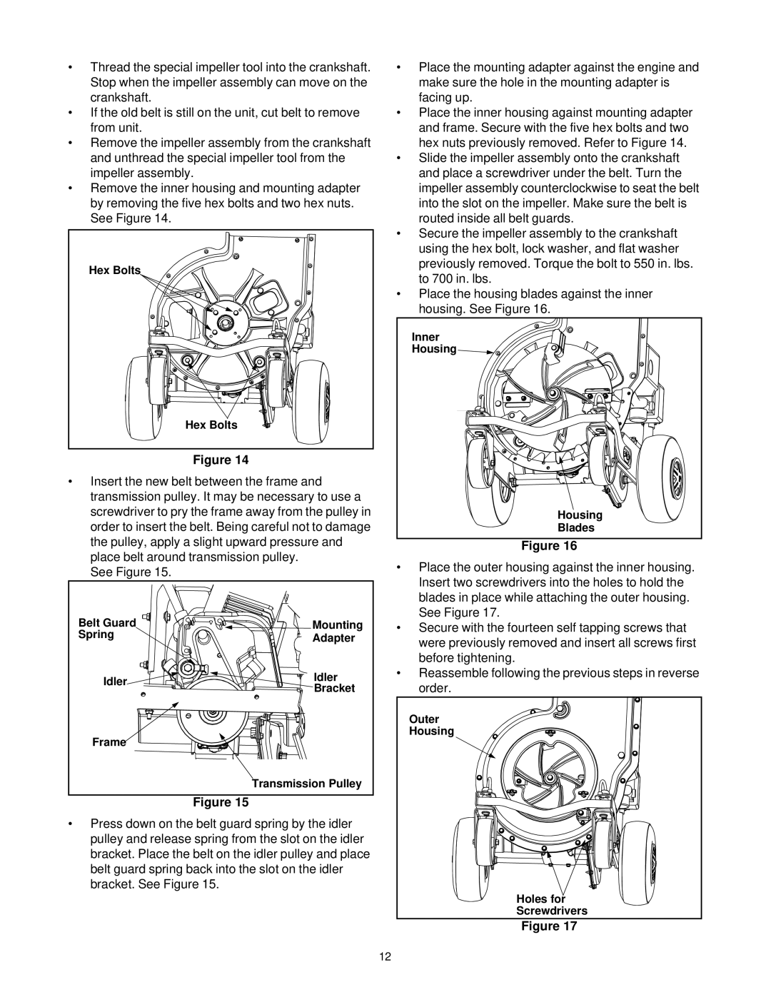
•Remove the inner housing and mounting adapter by removing the five hex bolts and two hex nuts. See Figure 14.
Hex Bolts |
Hex Bolts |
Figure 14
•Insert the new belt between the frame and transmission pulley. It may be necessary to use a screwdriver to pry the frame away from the pulley in order to insert the belt. Being careful not to damage the pulley, apply a slight upward pressure and place belt around transmission pulley.
See Figure 15.
Belt Guard | Mounting | |
Spring | Adapter | |
| ||
Idler | Idler | |
Bracket | ||
| ||
Frame |
| |
| Transmission Pulley |
Figure 15
•Press down on the belt guard spring by the idler pulley and release spring from the slot on the idler bracket. Place the belt on the idler pulley and place belt guard spring back into the slot on the idler bracket. See Figure 15.
•Place the mounting adapter against the engine and make sure the hole in the mounting adapter is facing up.
•Place the inner housing against mounting adapter and frame. Secure with the five hex bolts and two hex nuts previously removed. Refer to Figure 14.
•Slide the impeller assembly onto the crankshaft and place a screwdriver under the belt. Turn the impeller assembly counterclockwise to seat the belt into the slot on the impeller. Make sure the belt is routed inside all belt guards.
•Secure the impeller assembly to the crankshaft using the hex bolt, lock washer, and flat washer previously removed. Torque the bolt to 550 in. lbs. to 700 in. lbs.
•Place the housing blades against the inner housing. See Figure 16.
Inner |
Housing |
Housing |
Blades |
Figure 16
•Place the outer housing against the inner housing. Insert two screwdrivers into the holes to hold the blades in place while attaching the outer housing. See Figure 17.
•Secure with the fourteen self tapping screws that were previously removed and insert all screws first before tightening.
•Reassemble following the previous steps in reverse order.
Outer
Housing
Holes for
Screwdrivers
Figure 17
12