Brake Bracket Assembly | Auger Belt | assembly and secure with flat washer and cotter | |
pin. Reassemble the large shoulder bolt and lock | |||
Idler Pulley | |||
| washer. Refer to Figure 17. | ||
| Auger Pulley | ||
| • Reassemble belt cover and chute crank. | ||
|
| ||
|
| Changing Friction Wheel Rubber | |
|
| The rubber on the friction wheel is subject to wear and | |
|
| should be checked after the first 25 hours of operation, | |
|
| and periodically thereafter. Replace the friction wheel | |
|
| rubber if any signs of wear or cracking are found. | |
|
| • Drain the gasoline from the snow thrower, or place | |
|
| a piece of plastic under the gas cap. | |
|
| • Tip the snow thrower up and forward, so that it rests | |
|
| on the housing. | |
Belt Keepers | Hex Screw & | • Remove six screws from the frame cover | |
underneath the snow thrower. Refer to Figure 10. | |||
Belleville Washer | |||
| |||
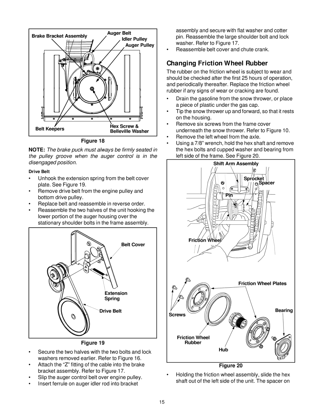
Figure 18 | • Remove the left wheel from the axle. | ||
• Using a 7/8” wrench, hold the hex shaft and remove | |||
|
| ||
NOTE: The brake puck must always be firmly seated in | the hex bolts and cupped washer and bearing from | ||
the pulley groove when the auger control is in the | left side of the frame. See Figure 20. | ||
disengaged position. |
| Shift Arm Assembly | |
Drive Belt |
|
| |
• Unhook the extension spring from the belt cover | Sprocket | ||
plate. See Figure 19. |
| Spacer | |
|
| ||
• Remove drive belt from the engine pulley and | Pin | ||
bottom drive pulley. |
| ||
|
| ||
• Replace belt and reassemble in reverse order. |
| ||
• Reassemble the two halves of the unit hooking the |
| ||
lower portion of the auger housing over the |
| ||
stationary shoulder bolts in the frame assembly. |
| ||
| Belt Cover | Friction Wheel | |
|
| ||
|
| Friction Wheel Plates | |
| Extension |
| |
| Spring |
| |
| Drive Belt | Bearing | |
|
| Screws | |
|
| Friction Wheel | |
Figure 19 | Rubber | ||
• Secure the two halves with the two bolts and lock | Hub |
| ||
|
|
| ||
washers removed earlier. Refer to Figure 16. |
|
|
| |
|
|
| ||
|
|
| ||
• Attach the “Z” fitting of the cable into the brake |
| |||
Figure 20 | ||||
bracket assembly. Refer to Figure 17. | • Holding the friction wheel assembly, slide the hex | |||
• Slip the auger control belt over engine pulley. | ||||
shaft out of the left side of the unit. The spacer on | ||||
• Insert ferrule on auger idler rod into bracket | ||||
|
|
| ||
15