•Tighten the two wing nuts already in place on the upper holes and secure the handles firmly.Slide the shift rod connector down over the end of the lower shift rod. Tap the connector until it locks over the lower shift rod. See Figure 2.
NOTE: If the connector is not properly assembled, the shift rod will pivot and you will not be able to change speeds or change directions.
•Remove the hairpin clip from the upper chute crank and slide the upper chute crank through the upper chute crank bracket and into the lower chute crank. Align the two holes on both chute cranks and insert the hairpin clip removed earlier, through these holes. See Figure 4.
Upper Chute Crank |
Upper Chute |
Crank Bracket |
Hairpin Clip |
Lower Chute Crank |
Figure 4
•If not already attached, slip the cables that run from the handle panel to the discharge chute into the cable guide located on top of the engine.
See Figure 5.
Discharge Chute |
Cable Guide |
Figure 5
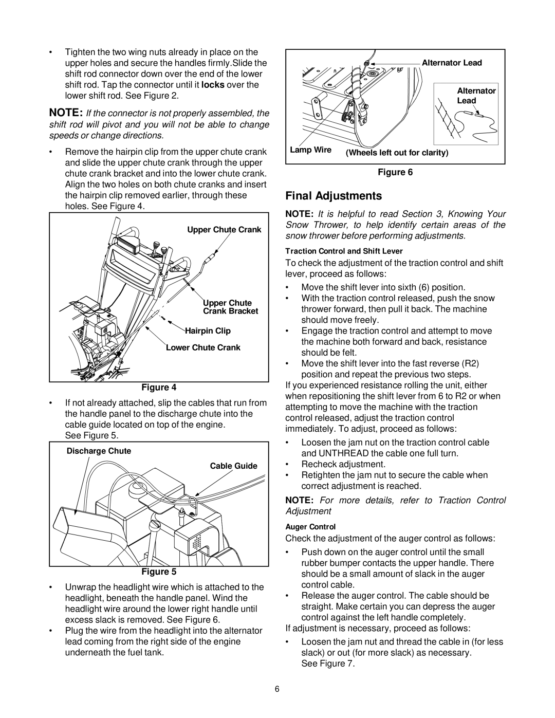
•Unwrap the headlight wire which is attached to the headlight, beneath the handle panel. Wind the headlight wire around the lower right handle until excess slack is removed. See Figure 6.
•Plug the wire from the headlight into the alternator lead coming from the right side of the engine underneath the fuel tank.
| Alternator Lead |
| Alternator |
| Lead |
Lamp Wire | (Wheels left out for clarity) |
|
Figure 6
Final Adjustments
NOTE: It is helpful to read Section 3, Knowing Your Snow Thrower, to help identify certain areas of the snow thrower before performing adjustments.
Traction Control and Shift Lever
To check the adjustment of the traction control and shift lever, proceed as follows:
•Move the shift lever into sixth (6) position.
•With the traction control released, push the snow thrower forward, then pull it back. The machine should move freely.
•Engage the traction control and attempt to move the machine both forward and back, resistance should be felt.
•Move the shift lever into the fast reverse (R2) position and repeat the previous two steps.
If you experienced resistance rolling the unit, either when repositioning the shift lever from 6 to R2 or when attempting to move the machine with the traction control released, adjust the traction control immediately. To adjust, proceed as follows:
•Loosen the jam nut on the traction control cable and UNTHREAD the cable one full turn.
•Recheck adjustment.
•Retighten the jam nut to secure the cable when correct adjustment is reached.
NOTE: For more details, refer to Traction Control Adjustment
Auger Control
Check the adjustment of the auger control as follows:
•Push down on the auger control until the small rubber bumper contacts the upper handle. There should be a small amount of slack in the auger control cable.
•Release the auger control. The cable should be straight. Make certain you can depress the auger control against the left handle completely.
If adjustment is necessary, proceed as follows:
•Loosen the jam nut and thread the cable in (for less slack) or out (for more slack) as necessary.
See Figure 7.
6